


GUIDELINE: Use ACP for managing coherency for small data size accesses,
manage coherency for large data in software.
3.6.4. FPGA Access to ACP via AXI or Avalon-MM
The AXI protocol allows masters to issue cacheable accesses whereas the Avalon-MM
protocol does not support this feature. For an FPGA master to perform a cacheable
access, the master must adhere to the AXI protocol and be able to perform cacheable
accesses, with
ARCACHE[1]
or
AWCACHE[1]
set to
1
and
ARUSER[0]
or
AWUSER[0]
set to
1
.
3.6.5. Data Alignment for ACP and L2 Cache ECC accesses
The L2 cache performs error detection and correction in groups of 64 bits without the
use of byte enables.
GUIDELINE: Accesses to the ACP must be 64-bit aligned, full 64-bit accesses,
and no byte lanes can disabled on write.
The main L3 switch and the ACP port are both 64 bits wide, so it is only necessary to
provide 64-bit aligned cache coherent accesses that are 64 bits wide after resizing.
Data resizing can occur in the L3 interconnect between requesting master and the
ACP. As a result, a 32-bit access can be compatible with the L2 cache ECC logic if the
access is aligned to 8-byte boundaries and the master performs bursts of size 2, 4, 8,
or 16. Data resizing can also occur within the FPGA-to-HPS bridge.
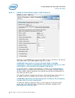
GUIDELINE: The simplest way to ensure that accesses from the FPGA meets
the L2 cache ECC requirements is to implement 64-bit masters in the FPGA
fabric and configure the FPGA-to-HPS bridge to expose a 64-bit slave port.
This ensures that no resizing of AXI transactions is necessary. Full 64-bit
accesses have to be made by the logic in the FPGA as well.
3.7. IP Debug Tools
The Intel Quartus Prime Design Software includes many IP and system-level debug
tools used in FPGA hardware designs.
The following tools are commonly used for system and IP debug in embedded
systems:
•
Signal Tap - On-chip logic analyzer constructed from FPGA resources
•
Bus functional models
— Avalon-MM v2 protocol
— AXI v3 protocol
•
System console - Services-based API for controlling soft logic and moving data to/
from the FPGA
Each debug tool is introduced at different stages of the hardware design. In a typical
hardware design flow, the developer follows these high-level verification steps:
3. Design Guidelines for HPS portion of SoC FPGAs
AN-796 | 2018.06.18
AN 796: Cyclone V and Arria V SoC Device Design Guidelines
26