background image


Intel

®

 RAID Software User’s Guide

153

5. Choose whether to have a snapshot taken on reboot. To enable this option, check the 

box next to the 

Take snapshot on reboot

 field. If you select this option, a snapshot is 

taken on boot after every successful shutdown. You can use this snapshot of the boot 

virtual drive to restore the operating system on the virtual drive in case the virtual drive 

becomes corrupted.

Caution:

Before you select this option, make sure that you backup all data to the virtual 

drive. If there is any existing data on this virtual drive, it will be lost after 

converting to the Snapshot repository.

6. Click 

OK

.

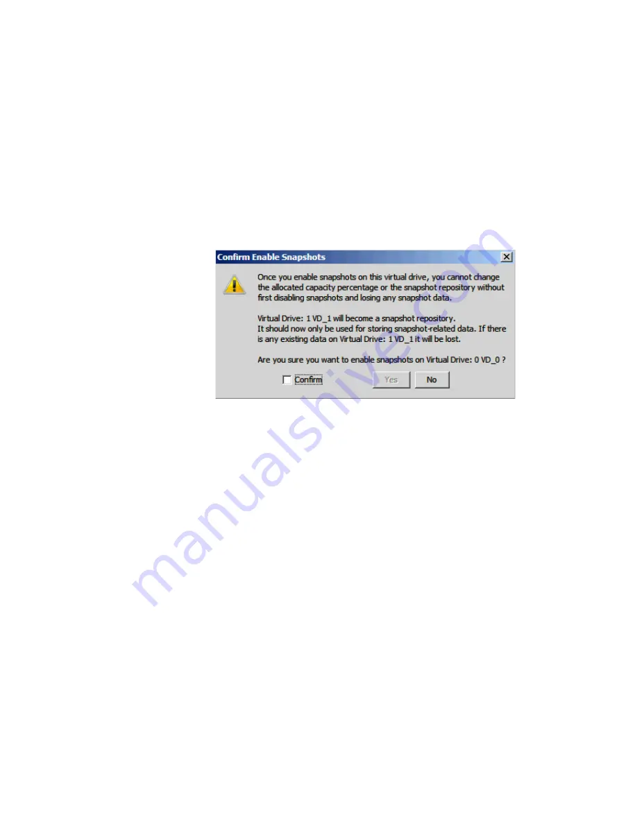
7. A confirmation dialog box appears. Check the box next to the Confirm field to enable 

snapshots on the selected virtual drive and then click 

Yes

.

Figure 108. Confirm Enable Snapshot

8. This virtual drive becomes a snapshot repository. Use it only for storing snapshot-

related data.

Caution:

After you enable snapshots on this virtual drive, you cannot change the 

allocated percentage of capacity or the snapshot repository without first 

disabling snapshots and losing any snapshot data.

Note:

With the current generation of the MegaRAID Recovery product there is no 

guidance on the size of the repository other than saying that it is completely 

dependent on the amount of data being written and the frequency of snapshots 

being taken. This is different in every application. Currently a customer will have 

to use empirical data on the behavior of their application to estimate this. If the 

repository runs out of space they will have to delete the oldest snapshot. Then at 

some time when it is appropriate they will have to disable the feature and re-

enable it, re-sizing the repository.

The existing snapshots are lost when the feature is disabled. Repository virtual 

drives will be lost if you disable snapshots.

In future development, users will be able to grow the size of the repository 

dynamically, without losing snapshots.

Summary of Contents for AFCSASRISER

Page 1: ...e User s Guide Intel Embedded Server RAID Technology 2 Intel IT IR RAID Intel Integrated Server RAID Intel RAID Controllers using the Intel RAID Software Stack 3 Revision 17 0 November 2011 Intel Order Number D29305 017 ...

Page 2: ...ING LIABILITY OR WARRANTIES RELATING TO FITNESS FOR A PARTICULAR PURPOSE MERCHANTABILITY OR INFRINGEMENT OF ANY PATENT COPYRIGHT OR OTHER INTELLECTUAL PROPERTY RIGHT Intel products are not intended for use in medical life saving life sustaining applications Intel may make changes to specifications and product descriptions at any time without notice Intel is a trademark or registered trademark of I...

Page 3: ...f RAID 5 and RAID 0 15 RAID 60 Combination of RAID 0 and RAID 6 16 RAID Configuration Strategies 19 Maximizing Fault Tolerance 19 Maximizing Performance 20 Maximizing Storage Capacity 21 RAID Availability 23 RAID Availability Concept 23 Spare Drives 23 Rebuilding 23 Copyback 23 Configuration Planning 24 Dimmer Switch Feature 24 Number of Physical Disks 25 MegaRAID Fast Path 25 4K Sector Drive Supp...

Page 4: ...isting Novell Netware System 38 RAID Driver Installation for Solaris 10 38 Installation in a New Solaris System 38 Installation in an Existing Solaris System 38 Chapter 5 Intel Embedded Server RAID BIOS Configuration Utility 39 Creating Adding or Modifying a Virtual Drive Configuration 40 Setting the Write Cache and Read Ahead Policies 42 Working with a Global Hot spare Drive 42 Adding a Hot spare...

Page 5: ...ating RAID 0 1 5 or 6 using Intel RAID BIOS Console 2 detailed 71 Creating RAID 10 RAID 50 and RAID 60 using Intel RAID BIOS Console 2 75 Setting Drive Parameters 80 Creating a Hot Spare 81 Viewing Event Details 84 Chapter 8 Intel RAID Web Console 2 87 Configuration Functions 87 Monitoring Functions 87 Maintenance Functions 88 Hardware and Software Requirements 88 Installing the Intel RAID Web Con...

Page 6: ...nfiguration from a Controller 126 Adding a Configuration from a File 127 Monitoring System Events and Devices 128 Monitoring System Events 128 Monitoring Controllers 129 Monitoring Disk Drives and Other Physical Devices 130 Monitoring Virtual Disks 133 Monitoring Enclosures 133 Monitoring Battery Backup Units 134 Battery Learn Cycle 135 Monitoring Rebuilds and Other Processes 137 Maintaining and M...

Page 7: ... Console 2 Add Physical Drives to Array 71 Figure 23 Intel RAID BIOS Console 2 Set Array Properties 72 Figure 24 Intel RAID BIOS Console 2 Confirm Configuration 73 Figure 25 Intel RAID BIOS Console 2 Initialization Speed Setting 74 Figure 26 Intel RAID BIOS Console 2 Multiple Disk Groups for RAID 10 50 or 60 75 Figure 27 Intel RAID BIOS Console 2 Spanning Multiple Arrays 76 Figure 28 Intel RAID BI...

Page 8: ...ow 112 Figure 62 Option to Create Additional Virtual Drives 113 Figure 63 Option to Close the Configuration Wizard 113 Figure 64 Assign Global Hotspare 115 Figure 65 Assign Dedicated Hotspare 116 Figure 66 Select Hotspare Drive 116 Figure 67 Set Adjustable Task Rates 117 Figure 68 Starting Modify Drive Group 119 Figure 69 Select RAID level to migrate 119 Figure 70 Selecting Drives to Add 120 Figur...

Page 9: ...napshot Base is shown 154 Figure 110 Enter Snapshot Name 154 Figure 111 Create Snapshot 155 Figure 112 Create View 155 Figure 113 Set MegaRAID Recovery Properties 156 Figure 114 Disable MegaRAID Recovery 157 Figure 115 Confirm Disable Snapshots 157 Figure 116 Adapter Selection 158 Figure 117 Selecting Snapshot Base 158 Figure 118 Selecting Advanced Operations 159 Figure 119 Selecting Rollback 159 ...

Page 10: ...x Intel RAID Software User s Guide Figure 137 Option to Create Additional Virtual Drives 172 Figure 138 Option to Close the Configuration Wizard 172 ...

Page 11: ...RAID 1E Overview 14 Table 6 RAID 10 Overview 15 Table 7 RAID 50 Overview 16 Table 8 RAID 60 Overview 17 Table 9 RAID Levels and Fault Tolerance 19 Table 10 RAID Levels and Performance 20 Table 11 RAID Levels and Capacity 22 Table 12 Factors to Consider for Array Configuration 26 Table 13 Intel RAID BIOS Console 2 Toolbar Icon Descriptions 62 Table 14 MFI Messages 174 ...

Page 12: ...xii Intel RAID Software User s Guide ...

Page 13: ...nd some that include the LSI 1068 SAS controller Intel Server Boards S3420GP Intel Server Boards S3200SH and X38ML Intel SAS Entry RAID Module AXX4SASMOD when the module is in ESRTII mode Intel RAID Controller SASMF8I Intel Embedded Server RAID Technology 2 provides driver based RAID modes 0 1 and 10 with an optional RAID 5 mode provided by Intel RAID C600 Upgrade Key RKSATA4R5 RKSATA8R5 RKSAS4R5 ...

Page 14: ...l RAID Activation Key AXXRAKSAS2 and a DDR2 667 MHz ECC DIMM to provide RAID modes 0 1 5 6 10 50 and 60 The Intel Integrated RAID Controller SROMBSASMR has a specially designed connector that only fits Intel Server Boards S5520HC S5500HCV S5520UR S5520SC and S5500WB12V S5500WB Note This manual does not include the software RAID modes provided by the SAS riser card on the Intel Server System S7000F...

Page 15: ...rovides one more feature of FDE Full Disk Encryption that RS2PI008 doesn t support Caution Some levels of RAID are designed to increase the availability of data and some to provide data redundancy However installing a RAID controller is not a substitute for a reliable backup strategy It is highly recommended you back up data regularly via a tape drive or other backup strategy to guard against data...

Page 16: ...iguration The only drive that the operating system works with is the virtual disk which is also called a virtual drive The virtual drive is used by the operating system as a single drive lettered storage device in Microsoft Windows The RAID controller is the mastermind that must configure the physical array and the virtual disks and initialize them for use check them for data consistency allocate ...

Page 17: ...t replaces In all three cases the failed drive is removed from the array If using a hot spare then the failed drive can remain in the system When a hot spare is available and an automatic rebuild starts the failed drive may be automatically removed from the array before the utilities detect the failure Only the event logs show what happened If the system is shut down during the rebuild all rebuild...

Page 18: ...d initialization is a consistency check that is forced five minutes after the creation of a virtual disk Background initialization also checks for media errors on physical drives and ensures that striped data segments are the same on all physical drives in an array Patrol read checks for physical disk errors that could lead to drive failure These checks usually include an attempt at corrective act...

Page 19: ...wo contiguous RAID 0 drives does not produce a new RAID level or add fault tolerance It does increase the size of the virtual volume and improves performance by doubling the number of spindles Spanning for RAID 10 RAID 50 and RAID 60 requires two to eight arrays of RAID 1 5 or 6 with the same stripe size and that always uses the entire drive CPU Usage Resource allocation provides the user with the...

Page 20: ...8 Intel RAID Software User s Guide ...

Page 21: ... independent parity blocks per stripe and disk striping A RAID 6 virtual disk can survive the loss of two disks without losing data RAID IME Integrated Mirroring Enhanced IME which supports mirrored arrays with three to ten disks plus hot spare disks This is implemented in Intel IT IR RAID RAID 10 A combination of RAID 0 and RAID 1 consists of striped data across mirrored spans It provides high da...

Page 22: ... level 0 is not fault tolerant If a drive in a RAID 0 array fails the whole virtual disk all physical drives associated with the virtual disk will fail By breaking up a large file into smaller segments the RAID controller can use both SAS drive and SATA drives to read or write the file faster RAID 0 involves no parity calculations to complicate the write operation This makes RAID 0 ideal for appli...

Page 23: ...o all drives RAID 5 is best suited for networks that perform a lot of small I O transactions simultaneously RAID 5 addresses the bottleneck issue for random I O operations Because each drive contains both data and parity numerous writes can take place concurrently Table 3 provides an overview of RAID 5 Uses Use RAID 1 for small databases or any other environment that requires fault tolerance but s...

Page 24: ...est loss of capacity Weak Points Not well suited to tasks requiring lot of writes Suffers more impact if no cache is used clustering If a drive is being rebuilt disk drive performance is reduced Environments with few processes do not perform as well because the RAID overhead is not offset by the performance gains in handling simultaneous processes Drives 3 to 32 RAID Adapter ABCDEF A C P3 B P2 E D...

Page 25: ...AID 5 Weak Points Not well suited to tasks requiring lot of writes A RAID 6 virtual disk has to generate two sets of parity data for each write operation which results in a significant decrease in performance during writes Disk drive performance is reduced during a drive rebuild Environments with few processes do not perform as well because the RAID overhead is not offset by the performance gains ...

Page 26: ... duplicates its data to its other drive The size of each block is determined by the stripe size parameter which is set during the creation of the RAID set RAID 10 supports up to eight spans Table 6 provides an overview of RAID 10 Uses Use RAID 1E for small databases or any other environment that requires fault tolerance but small capacity Strong Points Provides complete data redundancy RAID 1E is ...

Page 27: ... set RAID level 50 supports up to eight spans and tolerates up to eight drive failures though less than total disk drive capacity is available Though multiple drive failures can be tolerated only one drive failure can be tolerated in each RAID 1 level array Table 7 provides an overview of RAID 50 Uses Appropriate when used with data storage that requires 100 percent redundancy of mirrored arrays a...

Page 28: ...e blocks and then writes the blocks of data and parity to each drive in the array The size of each block is determined by the stripe size parameter which is set during the creation of the RAID set RAID 60 supports up to 8 spans and tolerates up to 16 drive failures though less than total disk drive capacity is available Each RAID 6 level can tolerate two drive failures Table 8 provides an overview...

Page 29: ...d drive Use for office automation online customer service that requires fault tolerance or for any application that has high read request rates but low write request rates Strong Points Provides data redundancy high read rates and good performance in most environments Each RAID 6 set can survive the loss of two drives or the loss of a drive while another drive is being rebuilt Provides the highest...

Page 30: ...ss all drives in the array Parity Q1 Q2 Segment 16 Segment 7 Parity P15 P16 Segment 15 Segment 11 Parity Q15 Q16 Parity P11 P12 RAID 6 RAID 6 RAID 0 Parity P3 P4 Parity Q3 Q4 Segment 3 Segment 6 Segment 4 Segment 10 Parity P3 P4 Parity Q9 ÄìQ1 Parity Q3 Q4 Segment 14 Segment 5 Parity P13 P14 Segment 13 Segment 9 Parity Q13 Q14 Parity P9 P10 Parity P5 P6 Parity Q5 Q6 RAID 60 ...

Page 31: ...tility allows a failed drive to be replaced and automatically rebuilt by hot swapping the drive in the same drive bay The RAID array continues to handle requests while the rebuild occurs providing a high degree of fault tolerance and zero downtime Table 9 RAID Levels and Fault Tolerance RAID Level Fault Tolerance 0 Does not provide fault tolerance All data is lost if any drive fails Disk striping ...

Page 32: ...rrays RAID 50 includes both parity and disk striping across multiple drives If a drive fails the RAID controller uses the parity data to recreate all missing information RAID 50 can sustain one drive failure per RAID 5 array and still maintain data integrity 60 Provides data redundancy using distributed parity across spanned RAID 6 arrays RAID 60 can sustain two drive failures per RAID 6 array and...

Page 33: ...fset by the performance gains in handling simultaneous processes 10 RAID 10 works best for data storage that need the enhanced I O performance of RAID 0 striped arrays which provides high data transfer rates Spanning increases the size of the virtual volume and improves performance by doubling the number of spindles The system performance improves as the number of spans increases the maximum numbe...

Page 34: ...e RAID set 6 RAID 6 provides redundancy for two drive failures without duplicating the contents of entire disk drives However it requires extra capacity because it uses two parity blocks per stripe This makes RAID 60 more expensive to implement 10 RAID 10 requires twice as many drives as all other RAID levels except RAID 1 RAID 10 works well for medium sized databases or any environment that requi...

Page 35: ...y state If a physical disk used in a RAID virtual disk fails a hot spare automatically takes its place and the data on the failed drive is rebuilt on the hot spare Hot spares can be used for RAID levels 1 IME 5 6 10 50 and 60 Note If a rebuild to a hot spare fails for any reason the hot spare drive will be marked as failed If the source drive fails both the source drive and the hot spare drive wil...

Page 36: ...virtual drive to the optimal state 2 The rebuild operation takes precedence over the copyback operation when the conditions exist to start both operations For example Where the hot spare is not configured or unavailable in the system There are two drives both members of virtual drives with one drive exceeding the SMART error threshold and the other failed If you add a hot spare assume a global hot...

Page 37: ...ndom block size IO activity typical of transactional database applications can sustain higher numbers of IO READs Per Second compared with Level 1 Fast Path The performance levels reached with this solution are equivalent to those of much costlier Flash based adapter card solutions Refer to Intel RAID Premium Feature Key AXXRPFKSSD AXXRPFKDE and AXXRPFKSNSH Installation Guide E88588 00x for descri...

Page 38: ...ese factors such as the following which are followed by suggested RAID levels for each situation Will this disk array increase the system storage capacity for general purpose file and print servers Use RAID 5 6 10 50 or 60 Does this disk array support any software system that must be available 24 hours per day Use RAID 1 IME 5 6 10 50 or 60 Will the information stored in this disk array contain la...

Page 39: ...in the same array Support for up to eight physical drives and eight virtual drives Stripe size of 64 KB only Support for disk coercion with options of None 128 MB or 1 GB Ability to select a virtual drive as boot device By default virtual drive 0 is bootable LSI MPT SAS BIOS Configuration Utility You can use the LSI MPT SAS BIOS Configuration Utility to create one or two IM IME volumes on each Int...

Page 40: ...ume with SAS disks Fusion MPT architecture Easy to use BIOS based configuration utility Error notification The drivers update an OS specific event log LED status support Write journaling which allows automatic synchronization of potentially inconsistent data after unexpected power down situations Metadata used to store volume configuration on mirrored disks Automatic background resynchronization w...

Page 41: ...e Intel RAID Web Console 2 allows you to Create and manage virtual drives Add a drive to a RAID virtual drive The following situations assume RAID 0 has one drive and RAID 1 has two drives convert from RAID 0 to RAID 1 by adding one additional drive convert from RAID 0 to RAID 5 by adding two additional drives convert from RAID 0 to RAID 6 by adding three additional drives convert from RAID 1 to R...

Page 42: ...rtition it as an additional drive or it may be added to an operating system drive depending upon the capability of the operating system Online RAID level migration allows for upgrading a RAID level Options are to go from RAID 1 to RAID 0 RAID 5 to RAID 0 RAID 6 to RAID 0 RAID 6 to RAID 5 With OCE options are to go from RAID 0 to RAID 1 RAID 0 to RAID 5 RAID 0 to RAID 6 RAID 1 to RAID 5 RAID 1 to R...

Page 43: ...atile Random Access Memory storage of array and disk group configuration information Array and disk group configuration information is stored both on the hard drive COD and in NVRAM This helps protect against loss of the configuration due to adapter and or drive failure Failed drives are automatically detected and a transparent rebuild of the failed array automatically occurs using a hot spare dri...

Page 44: ...d buffers additional consecutive stripes lines into cache Adaptive The read ahead automatically turns on and off depending upon whether the disk is accessed for sequential reads or random reads Background Tasks Rebuilding a failed drive is performed in the background The rebuild rate is tunable from 0 100 The rebuild rate controls the amount of system resources allocated to the rebuild Caution It ...

Page 45: ...ing on the RAID controller and drive enclosure the error may be evident by the color of LEDs the flashing of LEDs or audible alarms Audible Alarm The following list of beep tones is used on Intel Intelligent RAID Controllers These beeps usually indicate that a drive has failed Degraded Array or Disk Group Short tone 1 second on 1 second off Failed Array or Disk Group Long tone 3 seconds on 1 secon...

Page 46: ...34 Intel RAID Software User s Guide ...

Page 47: ...rosoft Windows XP operating system installation The system must contain an Intel RAID controller Microsoft Windows 2003 automatically adds the driver to the registry and copies the driver to the appropriate directory 1 Start the Microsoft Windows installation by booting from the Microsoft Windows CD ROM disk The system BIOS must support booting from a CD ROM drive You may need to change BIOS setti...

Page 48: ...e informs you that a nonsigned driver is being installed If you see this message click Continue Anyway 7 The system loads the driver from the Microsoft Windows driver disk and copies the driver to the system disk The Found New Hardware Wizard screen displays the message The wizard has finished 8 Click Finish to complete the driver upgrade RAID Driver Installation for Red Hat Enterprise Linux This ...

Page 49: ...ion procedure RAID Driver Installation for Novell NetWare Installation in a New Novell Netware System Follow the instructions in the Novell Netware Installation Guide to install Novell Netware in the server Perform the following steps to install Novell NetWare using your Intel RAID controller as a primary adapter Note Drivers for Novell Netware are not available on the CD ROM The latest drivers ar...

Page 50: ...lect a Driver screen displays Press Insert Follow the instructions that display Insert a disk into the floppy drive and press Enter The system will find and install the driver This completes the procedure RAID Driver Installation for Solaris 10 Installation in a New Solaris System This updated driver can be applied using the normal operating system installation options Note Drivers for Solaris 10 ...

Page 51: ...ives Set the boot drive Create a global hot spare drive View physical and virtual drive parameters View and set adapter properties including consistency check and auto resume SATA and SAS systems use different versions of the Intel Embedded Server RAID BIOS Configuration utility but both versions use the same keystrokes and contain identical menus The utility menus show limited help at the bottom ...

Page 52: ...Menu 4 Select a configuration method Easy Configuration does not change existing configurations but allows new configurations New Configuration deletes any existing arrays and virtual drives and creates only new configurations View Add Configuration lets you view or modify an existing configuration For each configuration method a list of available physical drives is displayed These drives are in t...

Page 53: ...ze By default all available space in the array is assigned to the current virtual drive For RAID 10 arrays only one virtual drive can be defined for the entire array 12 Optional Change the default Write Cache and Read Ahead policies See Setting the Write Cache and Read Ahead Policies 13 When you have finished defining the current virtual drive select Accept and press the Enter key 14 Repeat step 8...

Page 54: ...itten to the media of the drive the I O request is signaled as completed RA ON allows the read ahead mode of the physical drives which makes the virtual drive turn on In this mode the physical drive will read additoinal data and store that data into its cache This improves performance on sequential reads To change cache policies follow these steps 1 Select Objects Virtual Drive Virtual Drive n Vie...

Page 55: ...iled drives show the status FAIL 2 Press the arrow keys to highlight the physical drive that you want to rebuild Press the space bar to select the drive 3 Press the F10 key and select Y to confirm As the rebuild process begins the drive indicator shows REBLD 4 When the rebuild is complete press any key to continue Auto Rebuild and Auto Resume To ensure data protection enable Auto Rebuild and Auto ...

Page 56: ...dapter virtual drive and physical drive properties You can also change some adapter properties and the Write Cache and Read Ahead for Virtual Drives 1 From the Main Menu select Objects 2 Choose Adapter Virtual Drive or Physical Drive 3 Select the device from the list and view the properties For virtual drives choose View Update Parameters For physical drives choose Drive Properties The numeric val...

Page 57: ...ine If the drive was offline its status changes to ONLINE Configuring a Bootable Virtual Drive Follow these steps to configure a bootable virtual drive 1 From the Main Menu select Configure Select Boot Drive 2 Select a virtual drive from the list to make it the designated boot drive Note You should also check the system BIOS Setup utility for the boot order setting To access the BIOS Setup utility...

Page 58: ...46 Intel RAID Software User s Guide ...

Page 59: ...e used for the volume Features Integrated Mirroring and Integrated Mirroring Enhanced support the following featurs Configurations of one or two IM or IME volumes on the same Intel IT IR RAID Controller IM volumes have two mirrored disks IME volumes have three to ten mirrored disks Two volumes can have up to a total of 12 disks Note This feature requires IR RAID firmware v1 20 00 or above to be in...

Page 60: ...l load following initialization In this case the LSI MPT SAS BIOS Configuration Utility loads after the system has completed a power on self test You can configure one or two IM or IME volumes per Fusion MPT controller You can also configure one IM IME and one Integrated Striping IS volume on the same controller up to a maximum of 12 physical disk drives for the two volumes In addition you can cre...

Page 61: ...the volume change the No to Yes by pressing the or keys or the space bar When the first disk is added the utility prompts you to either keep existing data or overwrite existing data 6 Press M to keep the existing data on the first disk or press D to overwrite it If you keep the existing data this is called a data migration The first disk will be mirrored onto the second disk so any data you want t...

Page 62: ...ress Enter 4 When prompted to select a volume type choose Create IME Volume The Create New Array screen shows a list of disks that can be added to a volume 5 Move the cursor to the RAID Disk column and select a disk To add the disk to the volume change the No to Yes by pressing the or keys or the space bar 6 Repeat this step to select a total of three to ten disks for the volume All existing data ...

Page 63: ...dapter List screen use the arrow keys to select an Intel IT IR RAID Controller 2 Press Enter to go to the Adapter Properties screen shown in Figure 10 3 On the Adapter Properties screen use the arrow keys to select RAID Properties and press Enter 4 Continue with either step 4 in Creating an IM Volume on page 49 or step 4 in Creating an IME Volume on page 50to create a second volume Managing Hot Sp...

Page 64: ...volume s the hot spare disk must also be a SATA disk If SAS disks are used the hot spare disk must also be a SAS disk An error message appears if the selected disk is not the same type as the disks used in the IM IME volumes 5 Optional Select a second hot spare disk 6 Select Save changes then exit this menu to commit the changes The configuration utility pauses while the global hot spares are adde...

Page 65: ...nage Array and press Enter Synchronizing an Array The Synchronize Array command forces the firmware to resynchronize the data on the mirrored disks in the array It is seldom necessary to use this command because the firmware automatically keeps the mirrored data synchronized during normal operation When you use this command one disk of the array is placed in a degraded state until the data on the ...

Page 66: ...e too small or the wrong disk type the firmware deletes them as well Note When an IM volume is deleted the data is preserved on the primary disk When an IME volume is deleted the master boot records of all disks are deleted Locating a Drive or Multiple Drives in a Volume You can use the LSI MPT SAS BIOS Configuration Utility to locate and identify a specific physical disk drive by flashing the dri...

Page 67: ... B This controller will no longer have a disk designated as boot 5 To change the boot disk move the cursor to the new boot disk and press Alt B The boot designator will move to this disk Note The firmware must be configured correctly in order for the Alt B feature to work IS Configuration Overview You can use the LSI MPT SAS BIOS Configuration Utility to create one or two IS volumes with up to a t...

Page 68: ...umes that the required controller s and disks are already installed in the computer system You can configure an IM IME volume and an IS volume on the same Intel IT IR RAID Controller 1 On the Adapter List screen of the LSI MPT SAS BIOS Configuration Utility use the arrow keys to select a RAID adapter 2 Press Enter to go to the Adapter Properties screen as shown in Figure 13 Figure 13 Adapter Prope...

Page 69: ... a Second IS Volume The Intel IT IR RAID Controllers allow you to configure two IS volumes or an IS volume and an IM IME volume If one volume is already configured and if there are available disk drives there are two ways to add a second volume Option 1 Perform the following steps 1 In the LSI MPT SAS BIOS Configuration Utility select an adapter from the Adapter List Select the RAID Properties opt...

Page 70: ...e the current array press Enter when the Manage Array item is selected Activating an Array An array can become inactive if for example it is removed from one controller or computer and moved to another one The Activate Array option allows you to reactivate an inactive array that has been added to a system This option is only available when the selected array is currently inactive To activate an ar...

Page 71: ...ll disk drives in the volume Note The LEDs on the disk drives will flash as described above if the firmware is correctly configured and the drives or the disk enclosure supports disk location Selecting a Boot Disk You can select a boot disk in the SAS Topology screen This disk is then moved to scan ID 0 on the next boot and remains at this position This makes it easier to set BIOS boot device opti...

Page 72: ...60 Intel RAID Software User s Guide The boot designator will move to this disk Note The firmware must be configured correctly for the Alt B feature to work ...

Page 73: ...o guide you through the configuration of virtual drives and physical arrays Quick Configuration Steps This section provides the steps to configure arrays and disk groups and virtual drives using the Intel RAID BIOS Console 2 utility The following sections describe how to perform each action using the Intel RAID BIOS Console 2 utility The steps are as follows 1 Power on the system 2 Press Ctrl G to...

Page 74: ...etween the disks and the NVRAM the utility automatically displays the Select Configuration screen Choose whether the configuration should be read from the RAID array or from NVRAM For more information see Configuration Mismatch Screen on page 68 Screen and Option Descriptions This section describes the Intel RAID BIOS Console 2 screens and options Toolbar Options Table 13 describes the Intel RAID ...

Page 75: ...an Intel RAID controller and switch between the Physical Drives view and Virtual Drives view The main screen also provides access to the following screens and tools Controller Selection Controller Properties Scan Devices Virtual Drives Drives Configuration Wizard Physical View Events Exit Figure 15 Intel RAID BIOS Console 2 Menu ...

Page 76: ...ows you to view and configure the software and hardware of the selected controller Figure 17 Controller Properties Firmware Version The firmware version Host Interface The host interface for the installed RAID controller NVRAM Size The NVRAM size on the RAID controller Firmware Time The firmware release date time Min Stripe Size The minimum stripe size used to read and write data WebBIOS Version T...

Page 77: ...Enter a number between 0 and 100 to control the rate at which a future rebuild will be performed on a disk group Patrol Read Rate A patrol read is a preventive procedure that monitors physical disks to locate and resolve potential problems that could lead to disk failure Enter a number between 0 and 100 to control the rate at which patrol reads are performed BGI Rate Background Initialization Rate...

Page 78: ... Spinup Delay After the RAID controller completes its initialization process the initial delay value defines the number of seconds before the first disk interrogation request is issued to the array or disk group Do not change this value Stop On Error Stops system POST if any error is detected NCQ Enables NCQ Native Command Queuing to optimize physical drive performance and life Stop CC On Error St...

Page 79: ...anges Physical Drives Screen This screen displays the physical drives for each channel or port From this screen you can rebuild the physical arrays or disk groups or view the properties for the physical drive you select Click Reset to return to the configuration that existed before you made any changes Select Properties and click Go to view the properties An unconfigured drive can be made into a h...

Page 80: ...ion Select View Disk Configuration to restore the configuration from the hard disk Select View NVRAM Configuration to restore the configuration from the NVRAM Setting Up a RAID Array Using the Configuration Wizard This section provides detailed steps for using the Configuration Wizard to set up a RAID array 1 Start the Configuration Wizard by selecting the Configuration Wizard icon on the Intel RA...

Page 81: ...Intel RAID Software User s Guide 69 Figure 20 Selecting Configuration ...

Page 82: ...ith three or more drives or RAID 6 for systems with three or more drives All available physical drives are included in the virtual drive using all available capacity on the disks No Redundancy configures all available drives as a RAID 0 virtual drive There is a Drive Security Method option which is reserved to be enabled in future Note You must designate hot spare drives before starting auto confi...

Page 83: ...2 Select a controller and click Start to begin the configuration 3 Choose Manual Configuration and click Next see Figure 21 4 At the Disk Group Definition DG Definition screen hold down the Ctrl key and click each drive you want to include in the array or disk group See RAID Levels on page 9 for the required minimum number of drives that must be added Figure 22 Intel RAID BIOS Console 2 Add Physic...

Page 84: ... needed change the Stripe Size the policies for Access Read Write IO and Disk Cache and decide whether to use background initialization For information about setting these parameters see Setting Drive Parameters on page 80 Figure 23 Intel RAID BIOS Console 2 Set Array Properties 11 Click Accept to accept the changes or click Reclaim to delete the changes and return to the previous settings The Int...

Page 85: ...are User s Guide 73 Figure 24 Intel RAID BIOS Console 2 Confirm Configuration 13 Click Accept as necessary in the screens that follow You are prompted to save the configuration and then to initialize the virtual drive ...

Page 86: ... runs full initialization in the background after the operating system is booted Slow initialization may take several hours or even days to complete Figure 25 Intel RAID BIOS Console 2 Initialization Speed Setting 16 Click Home to return to the main configuration screen 17 Select an additional virtual drive to configure or exit the Intel RAID BIOS Console 2 configuration utility and reboot the sys...

Page 87: ...ick each drive you want included in the first array For RAID 10 use two drives For RAID 50 use at least three drives For RAID 60 use at least three drives 5 Click Add To Array and then click Accept DG in the right pane to confirm The first group of drives appears as a disk group in the right pane These drives are no longer available in the left pane 6 From the drives that are available in the left...

Page 88: ... screen select either RAID 10 RAID 50 or RAID 60 from the RAID Level drop down RAID 10 is illustrated below 12 Select the appropriate Stripe Size Access Policy Read Policy Write Policy IO Policy Disk Cache Policy and Enable Disable BGI for your application For information about setting these parameters see Setting Drive Parameters on page 80 13 Set the drive size to a number in MB that is a size g...

Page 89: ...l RAID BIOS Console 2 Viewing Completed Settings 15 Click Accept to save the configuration 16 When asked to save the configuration click Yes This will store the configuration in the RAID controller 17 When asked to initialize the drive click Yes 18 Select Fast Initialize and click Go The drives will initialize based on the RAID settings Note Slow Initialize initializes the entire drive and may tak...

Page 90: ...o return to the main screen The RAID 10 RAID 50 or RAID 60 virtual drives are displayed The following figure shows the RAID 10 virtual drives Figure 30 Intel RAID BIOS Console 2 RAID 10 Final Screen 20 Under Virtual Drives select Virtual Drive 0 RAID 10 or select Virtual Drive 0 RAID 50 or select Virtual Drive 0 RAID 60 to display the drive properties ...

Page 91: ...Intel RAID Software User s Guide 79 Figure 31 Intel RAID BIOS Console 2 RAID 10 Properties Screen Figure 32 Intel RAID BIOS Console 2 RAID 50 Properties Screen ...

Page 92: ...f the two most recent disk accesses occurred in sequential sectors Write Policy Determines when the transfer complete signal is sent to the host Write through caching is the default setting Write back caching Further classified as Write Back with BBU or Always Write Back which means Write Back is always enabled even if BBU is bad or missing The controller sends a data transfer completion signal to...

Page 93: ...k cache policy unchanged Disable BGI Enable or disable background initialization Set this option to Yes to disable background initialization Select Size Set the size of the virtual drive in megabytes The right pane of the virtual drive configuration window lists the maximum capacity that can be selected depending on the RAID level chosen Creating a Hot Spare To create a hot spare follow these step...

Page 94: ...n virtual drives Click Make Global HSP if you want to create a global hot spare for all disk groups Figure 34 Intel RAID BIOS Console 2 Setting a Hot Spare Drive 4 Click Go to create the hot spare The Drive State changes to HOTSPARE as shown below Figure 35 Intel RAID BIOS Console 2 Viewing Hot Spare 5 Click Home to return to the main screen ...

Page 95: ...Intel RAID Software User s Guide 83 Figure 36 Intel RAID BIOS Console 2 Main Screen showing Hot Spare Drive ...

Page 96: ... the Main screen select Events from the menu at the left The Events screen appears Figure 37 Intel RAID BIOS Console 2 Event Information Screen 2 Select the component to display from the Event Locale list 3 Select the type of event to display from the Event Class drop down 4 Type the Start Sequence and the of Events to display The following example shows a selection that was made for informational...

Page 97: ...ges were selected starting with the event at sequence 120 The events screen displays the event information for sequence number 120 in the right pane Note In the following example the Start Sequence and the of Events fields display 0 This is because when you click Go to display the events these fields automatically reset to 0 Figure 39 Intel RAID BIOS Console 2 Viewing an Event ...

Page 98: ...86 Intel RAID Software User s Guide 6 Click Next to view the next message ...

Page 99: ...ailable hardware Note Auto Configuration cannot be used for RAID 10 50 or 60 or with mixed SATA and SAS drives Guided Configuration mode asks you a few brief questions about the configuration and then creates the array for you Manual Configuration mode gives you complete control over all aspects of the storage configuration The Reconstruction Wizard enables you to increase or reduce the size of a ...

Page 100: ...t Windows Server 2003 Microsoft Windows Server 2008 or Microsoft Windows XP Red Hat Linux Enterprise 3 0 4 0 or 5 0 with or without corresponding service packs SuSE Enterprise Linux 9 0 10 0 or 11 0 with or without corresponding service packs VMWare ESX 3i 4i Installing the Intel RAID Web Console 2 on a Microsoft Windows Operating System To install the Intel RAID Web Console 2 on a Microsoft Windo...

Page 101: ...dministrative privileges can view or change the RAID configurations If you select Only for current user Administrator only you can view or change the RAID configurations 5 Click Next to continue 6 Accept the default Destination Folder or click Change to select a different destination folder Click Next to continue The Setup Type screen is displayed as shown in Figure 41 Figure 41 Setup Type Screen ...

Page 102: ...ree setup options are the same as those shown in step 7 of the Microsoft Windows installation instructions Intel RAID Web Console 2 Support and Installation on VMWare This section documents the installation of Intel RAID Web Console 2 on VMWare Classic with console operating system and on the VMWare ESX 3i operating system Installing Intel RAID Web Console 2 for VMWare Classic VMWare does not supp...

Page 103: ...a key element for a proper setup Therefore we recommend that you install the management on a VM within the ESXi Follow these steps to install and configure Intel RAID Web Console 2 support on the VMWare ESX operating system 1 Network Configuration of the ESXi Host Assignment of a ESXi hostname Even if it is not relevant for your network you need a FQDN Fully Qualified Domain Name Example local lsi...

Page 104: ...or the controller There is no user authentification Events are collected as long as Intel RAID Web Console 2 runs on the Client Intel RAID Web Console 2 responds more slowly Differences in Intel RAID Web Console 2 for VMware ESXi The following are some of the differences in the Intel RAID Web Console 2 utility when you manage a VMWare server 1 The following limitations apply to the system informat...

Page 105: ...inux Solaris hosts 4 Remote discovery and heartbeat mechanism For networks that do not have DNS configured the hosts file in the machine on which the Intel RAID Web Console 2 is installed must be edited as follows Add an entry to map the VMWare host s IP address with the hostname This is for the discovery to happen correctly In the absence of this entry the VMWare host would be discovered as 0 0 0...

Page 106: ...d libsysfs libraries as follows ls lrt libcrypto ls lrt libssl ls lrt libsysfs If the files libcrypto so 4 libssl so 4 and libsysfs so 1 are missing manually create sym links as follows ln s libcrypto so libcrypto so 4 ln s libssl so libssl so 4 ln s libsysfs so libsysfs so 1 If the so files are not present in the usr lib directory create a link with the existing version of the library For example...

Page 107: ... Kill 9 inetd pid c Type the following command to restart the inetd daemon inetd 4 Type the following command to use scp to copy storelib from a remote machine to the following path lib dir scp user ip path to storelib libstorelib so 2 53 lib libstorelib so 5 Restart SFCB and check its status a Type the following command to restart SFCB etc init d sfcbd restart b Type the following command to chec...

Page 108: ...tartupUI Intel RAID Web Console 2 Screens This section describes the main Intel RAID Web Console 2 screens When you start the Intel RAID Web Console 2 the Select Server window is displayed Note Depending on the revision of Intel RAID Web Console 2 software installed the following screen may vary slightly Figure 42 Intel RAID Web Console 2 Select Server Screen Note To access systems on a different ...

Page 109: ...down menu Select Full Access if you need to view the current system configuration and change the configuration Select View Only if you only need to view the system configuration 3 Enter your user name and password and click Login If your user name and password are correct for the login mode you have chosen the main screen displays Note Intel RAID Web Console 2 uses the username and password of you...

Page 110: ...el RAID Web console 2 dashboard The information displayed on this Dashboard screen provides an overview of the RAID ecosystem on the selected server system Some frequently used functions are listed in the Dashboard tab such as Create Virtual Drive etc ...

Page 111: ...e Physical View or the Virtual View of the system and the devices in it Note The word Virtual maybe displayed as Logical depending on different versions of the utility The Physical View shows the hierarchy of physical devices in the system At the top of the hierarchy is the system itself Controllers are installed in the system and each controller has one or more ports Disk drives and other physica...

Page 112: ...a disk drive Properties Operations Graphical View Panel Depending on the kind of device selected in the left panel and your login mode full access or view only the right panel has either two or three tabs The Properties tab displays information about the selected device Note Depending on different Intel R RAID Web Console 2 versions Operations and Graphical tabs may not exist or only exist in old ...

Page 113: ...panel the Graphical tab is available in the right panel In the Graphical View the device s storage is color coded to show used capacity unused capacity and so on Note This Graphical View feature may or may not be displayed in the utility depending on the version of the utility Figure 47 Intel RAID Web Console 2 Graphical Tab Optional feature Event Log Panel The lower part of the screen displays th...

Page 114: ...xample if an offline physical drive is selected the Make Drive Online option is displayed in the menu There is a general tip here that most functions in the Go To menu are equal to right clicking the storage object selected in Physical or Logical view tab For example selecting Go To Controller Create Virtual Drive is equal to selecting the controller in Physical or Logical tab right clicking it an...

Page 115: ...g virtual drives Note Unless you are logged on to a system with Administrator privileges you cannot create or modify a storage configuration Creating a Virtual Drive Using Simple Configuration Simple configuration is the quickest and easiest way to create a new storage configuration When you select simple configuration mode the system creates the best configuration possible using the available dri...

Page 116: ...04 Intel RAID Software User s Guide Figure 48 Virtual Drive Creation Menu The dialog box for the configuration mode simple or advanced appears as shown in Figure 49 Figure 49 Virtual Drive Creation Mode ...

Page 117: ...tual drive Hot spares are drives that are available to replace failed drives automatically in a redundant virtual drive RAID 1 RAID 5 or RAID 6 Note In the simple configuration procedure you can assign dedicated hot spares to a maximum of 16 arrays at one time This is because the dedicated hot spares can support only up to 16 drive groups If you try to create more than 16 drive groups at one time ...

Page 118: ...figuration is completed a dialog box may or may not notify depending on different utility version you that the virtual drives were created successfully as shown in Figure 52 If more drive capacity exists the dialog box asks whether you want to create more virtual drives If no more drive capacity exists you are prompted to close the configuration session Figure 52 Option to Create Additional Virtua...

Page 119: ...tion because you can select the drives and the virtual drive parameters when you create a virtual drive In addition you can use the advanced configuration procedure to create spanned drive groups Follow these steps to create a new storage configuration in the advanced configuration mode In this example we will create a spanned drive group 1 Perform either of the following steps Right click on the ...

Page 120: ...108 Intel RAID Software User s Guide Figure 54 Virtual Drive Creation Menu The dialog box shown in Figure 55 appears Figure 55 Virtual Drive Creation Mode ...

Page 121: ...Drive Group 0 and Span 0 appear in the Drive groups field when you select RAID 10 50 or 60 The RAID controller supports RAID levels 1 5 6 10 50 and 60 In addition it supports independent drives configured as RAID 0 and RAID 00 The screen text gives a brief description of the RAID level you select RAID levels you can choose depend on the number of drives available To learn more about RAID levels se...

Page 122: ...Create Span to create a second span in the drive group d Select unconfigured drives from the list of drives and click Add to add them to the drive group e The selected drives appear under Span 1 below Drive Group 0 as shown in Figure 58 Figure 58 Span 0 and Span 1 of Drive Group 0 ...

Page 123: ...virtual drive or remove the virtual drive are grayed out until you create the virtual drive Figure 59 Virtual Drive Settings Window 4 Change any virtual drive settings if desired 5 Click Create Virtual Drive The new virtual drive appears under the drive group as shown in Figure 60 The options Update Virtual Drive and Remove Virtual Drive are now available Update Virtual Drive allows you to change ...

Page 124: ...figuration Figure 61 Create Virtual Drive Summary Window 7 Click Back to return to the previous screen to change any selections or click Finish to accept and complete the configuration The new storage configuration will be created and initialized Note If you create a large configuration using drives that are in powersave mode it could take several minutes to spin up the drives A progress bar appea...

Page 125: ...city exists you are prompted to close the configuration session Figure 62 Option to Create Additional Virtual Drives 9 Select Yes or No to indicate whether you want to create additional virtual drives If you select Yes the system takes you to the Create Virtual Drive screen as shown in Figure 50 If you select No the utility asks whether you want to close the wizard as Figure 63 10 If you selected ...

Page 126: ... and storage capacity The Intel RAID Web Console 2 supports three types of spanned arrays or disk groups RAID 00 multiple RAID 0 arrays or disk groups RAID 10 multiple RAID 1 arrays or disk groups RAID 50 multiple RAID 5 arrays or disk groups RAID 60 multiple RAID 6 arrays or disk groups For spanned disk group creation steps refer to the section Creating a Virtual Drive Using Advanced Configuratio...

Page 127: ...n If it is assigned to a storage configuration a check mark is displayed on the disk drive icon 2 In the Menu click the Go To Physical Drive tab and select Assign Global Hotspare as shown in Figure 64 Figure 64 Assign Global Hotspare You normally create a dedicated hot spare when you create a new configuration with the Manual Configuration option To add a dedicated hot spare to an existing array o...

Page 128: ...ntel RAID Software User s Guide Figure 65 Assign Dedicated Hotspare 3 Select the array or disk group to which the hotspare will be dedicated from the list in the pop up window Figure 66 Select Hotspare Drive ...

Page 129: ...own in Figure 67 Figure 67 Set Adjustable Task Rates 3 Enter changes as needed to any of the task rates Rebuild Rate Enter a number from 0 to 100 to control the rate at which a rebuild is performed on a disk drive when one is necessary The higher the number the faster the rebuild will occur However if a higher number is selected the system I O rate may be slower Patrol Rate Enter a number from 0 t...

Page 130: ...truction of a virtual disk occurs The higher the number the faster the reconstruction will occur However if a higher number is selected the system I O rate may be slower 4 Click OK to accept the new task rates 5 When the warning message is displayed click OK to confirm that you want to change the task rates Note The Controller Go To tab also has options for disabling or silencing the alarm on the ...

Page 131: ...shown in Figure 69 Figure 69 Select RAID level to migrate 2 Click Add Drive Note Depending on current RAID level the targeted migrated RAID level and the available Unconfigured Good drive numbers pop up window may appear to allow selection among Add drives Remove drives and Migrate RAID level The following screen appears ...

Page 132: ...t The next screen displays which allows you to review the summary and go back if you need to make corrections as shown in Figure 71 Figure 71 Changing RAID Level 5 When everything is acceptable click Finish to accept the new configuration A Reconstruct operation begins on the virtual disk You can monitor the progress of the reconstruction in the Group Show Progress window Select Manage Show Progre...

Page 133: ... as described in the previous section 2 Click Remove Drive Note Depending on current RAID level the targeted migrated RAID level and the available Unconfigured Good drive numbers pop up window may appear to allow selection among Add drives Remove drives and Migrate RAID level The following screen appears Figure 72 Selecting Drives to Remove 3 In the panel check the disk drives that you want to rem...

Page 134: ...ogress window Select Manage Show Progress Changing Virtual Disk Properties You can change a virtual disk s Read Policy Write Policy and other properties after the disk is created To do this follow these steps 1 Select a virtual disk or drive icon in the left panel and then select Go To Virtual Drive Set Virtual Drive Properties Alternatively click the Properties panel and then click Set Virtual Di...

Page 135: ...disks Before you can do this you must be logged on to the system in All Access mode To delete a virtual disk follow these steps 1 Back up all user data on the virtual disk you intend to delete 2 In the left panel select the Virtual or Logical tab and click the icon of the virtual disk or drive you want to delete 3 In the menu select the Go To Virtual Drive and click Delete Virtual Drive 4 When the...

Page 136: ...g the existing configuration from that controller In order to do this you must be logged on to the system in All Access mode This section explains how to do these tasks Saving a Configuration to Disk You can save an existing controller configuration to a file so you can apply it to another controller To save a configuration file follow these steps 1 Select a controller icon in the left panel of th...

Page 137: ...25 The Save dialog box displays as shown in Figure 76 Figure 76 Save Configuration Dialog Box 3 In the dialog box type a name for the configuration file 4 Click Save to save the configuration file or accept the default name hostname cfg ...

Page 138: ...lear a configuration make sure to save any data you want to keep Clearing a configuration deletes all data from the disks in the existing configuration To clear a configuration from a controller follow these steps 1 Select a controller icon in the left panel of the Intel RAID Web Console 2 window 2 Select Go To Controller Clear Configuration Figure 77 Clear Configuration A Warning message displays...

Page 139: ... of the physical disks connected to the controller is exactly the same as it was when the configuration was saved To add a saved configuration follow these steps 1 Select a controller icon in the left panel of the Intel RAID Web Console 2 window 2 Select Go To Controller Load Configuration Figure 78 Add Saved Configuration A Warning message displays 3 Click Yes 4 When the Open dialog box is displa...

Page 140: ... right click the BBU icon to open the operations menu and select Start Learn Cycle Monitoring Rebuilds and Other Processes Monitoring System Events Intel RAID Web Console 2 monitors the activity and performance of all controllers in the system and the devices attached to them When an event occurs such as the completion of a consistency check or the removal of a physical drive an event message disp...

Page 141: ...lear Clears the current log information if you have full access versus View only access Load Enables you to load a local log file When a local log is displayed the status bar lists the name of the local log file and the Log menu has an additional option Rollback to Current Log which enables you to retrieve the system log Monitoring Controllers When Intel RAID Web Console 2 is running you can see t...

Page 142: ...d Other Physical Devices When the Intel RAID Web Console 2 is running you can see the status of all physical disk drives and other physical devices in the left panel If the physical drive is operating normally the controller icon looks like this If the physical drive has failed a small red circle is displayed to the right of the icon To display complete physical drive Information click on a physic...

Page 143: ... Locating Drive see Figure 82 Figure 82 Locating a Physical Drive The LED on the physical disk drive in the enclosure starts blinking to show its location Note LEDs on global or dedicated hot spare drives do not blink 4 To stop the disk drive light from blinking click Stop Locating Drive ...

Page 144: ...ion 3 Select an Operation Mode for patrol read The options are Automatic Patrol Read runs automatically at the time interval you specify on this screen Manual Patrol Read runs only when you manually start it by selecting Start Patrol Read from the controller options screen see Figure 83 Disabled Patrol Read does not run at all 4 Optional Specify a maximum count of physical drives to include in the...

Page 145: ...ks 1 2 and 3 Multiple virtual disks can use the same physical disk To display complete virtual disk information click the Virtual tab in the left panel click on a virtual disk icon in the left panel Figure 84 shows the Properties tab for a virtual disk in the right panel Figure 84 Virtual Drive Properties The RAID level stripe size and access policy of the virtual disk are set when it is configure...

Page 146: ...the status of all of the BBUs connected to controllers in the server If a BBU is operating normally the icon looks like this If it has failed a red dot appears next to the icon To show the properties for a BBU perform the following steps 1 Click the Physical tab on the main menu to open the physical view 2 Select the BBU icon in the left panel The BBU properties such as the battery type temperatur...

Page 147: ...ormed by the controller periodically to determine the condition of the battery You can start battery learn cycles manually or automatically To choose automatic battery learn cycles enable automatic learn cycles To choose manual battery learn cycles disable automatic learn cycles If you enable automatic learn cyles you can delay the start of the learn cycles for up to 168 hours 7 days If you disabl...

Page 148: ... next learn cycle field 6 To disable automatic learn cycles click Disable automatic learn cycles and click Go You can start the learn cycles manually In addition you can check the box next to the field Remind me when to start a learn cycle to receive a reminder to start a manual learn cycle Starting a Learn Cycle Manually To start the learn cycle properties manually perform the following steps 1 C...

Page 149: ... Window Operations on virtual disks appear in the left panel of the window and operations on physical drives appear in the right panel The types of operations that appear in this window are as follows Initialization of a virtual disk see Initializing a Virtual Disk on page 138 Rebuild see Rebuilding a Drive on page 140 Reconstruction see Adding a Drive to a Virtual Disk on page 118 Consistency che...

Page 150: ...ncy Check Rebuilding a Drive Removing a Drive Flashing the Firmware Initializing a Virtual Disk When you create a new virtual disk with the Configuration Wizard you can choose to initialize the disk initialized immediately To initialize a virtual disk after the configuration process follow these steps 1 Select the Virtual tab in the left panel and click the icon of the virtual disk to initialize 2...

Page 151: ...y check scans the virtual disk to determine whether consistency data is corrupted and needs to be restored It is especially important to do this if you suspect that the virtual disk consistency data is corrupted To run a consistency check follow these steps 1 Select Manage Check Consistency The Group Consistency Check window is displayed as shown in Figure 90 Figure 90 Group Consistency Check Wind...

Page 152: ...stem fails the system is protected from data loss by the parity data in RAID 5 RAID 50 or RAID 60 or by data redundancy RAID 1 RAID 10 You must replace the failed drive and rebuild the drive s data on a new drive to restore the system to fault tolerance Or if the drive is still operational you can rebuild the data on the failed drive If dedicated or global hot spare disks are available the failed ...

Page 153: ...d replace it with a new drive of equal or greater capacity When the new drive spins up the drive icon changes to green and the rebuild begins automatically You can monitor the progress of the rebuild in the Group Show Progress window by selecting Manage Show Progress Note If you want to force a disk drive into Fail status to trigger a rebuild right click the drive icon and select Make Drive Offlin...

Page 154: ... The controller is updated with the new firmware code contained in the ROM file Enabling RAID Premium Features Enabling Full Disk Encryption feature This feature is supported by Intel RAID controller RS2BL080DE RS2PI008DE and by other controllers with Intel RAID Premium Feature Key AXXRPFKDE installed This feature also requires that Self Encrypting Drives SEDs are connected to the RAID controller ...

Page 155: ...a logical volume containing Self Encrypting Disks Specify that the volume be secured Detailed steps are as below 1 Select the RAID controller and choose Physical tab in the left panel of Intel RAID Web Console 2 Check Drive Security Properties in the right panel to see whether the RAID controller is Drive Security capable Figure 93 Check Controller Security status 2 Select the physical drive and c...

Page 156: ... Intel RAID Software User s Guide Figure 94 Check Drive Security status 3 Right click on the controller and select Enable Drive Security Figure 95 Enable Drive Security 4 In the Security Wizard click Next ...

Page 157: ...AID Software User s Guide 145 Figure 96 Start Security Wizard 5 Create the required Security key Identifier Use the default suggestion or create your own then click Next Figure 97 Enter Security Key Identifier ...

Page 158: ...ftware User s Guide 6 Create the required Security key Use the default suggestion or create your own then click Next Figure 98 Enter Security Key 7 Create an optional Pass Phrase for additional security then click Next ...

Page 159: ...Intel RAID Software User s Guide 147 Figure 99 Enter Pass Phrase 8 Accept the confirmation to complete the wizard and enable drive security then click Finish Figure 100 Confirm Enable Drive Security ...

Page 160: ...ler properties now indicate Drive security enabled is Yes Figure 101 Check Drive Security Enabled status 10 Select Unconfigured Good drives and select Drive security method here FDE to create the virtual drive Figure 102 Select Full Disk Encryption ...

Page 161: ...Log information at the bottom of the window also indicates the virtual drive security status Full Disk Encryption feature has now been enabled Figure 103 Create RAID Virtual Drive with FDE enabled 12 Optional For Self Encrypting Drives SEDs that need to have their data permanently erased for security reason follow normal steps to delete the secured RAID virtual drive and mark all SEDs as Unconfigu...

Page 162: ...150 Intel RAID Software User s Guide Figure 104 Instant Secure Erase 13 Accept confirmation to permanently erase disk drive Figure 105 Confirm Secure Erase ...

Page 163: ...previous point in time Recovers lost data from disk in minutes minimizing the downtime experienced by users and eliminating the lengthy process of restoring data from tape Allows isolation of a server s boot volume to a separate virtual drive by enabling the Auto Snapshot feature users are guaranteed that bootable snapshots exist in case corruption of operating system occurs Note MegaRAID Recovery...

Page 164: ...hot Repository in the Snapshot Repository field You can leave the suggested virtual drive as the Snapshot Repository 4 Enter the capacity to use in the Snapshot Repository for changes to the base virtual drive The available capacity is the largest free block of capacity on the snapshot repository virtual drive Figure 107 Enter the Capacity for Snapshot Respository ...

Page 165: ...r storing snapshot related data Caution After you enable snapshots on this virtual drive you cannot change the allocated percentage of capacity or the snapshot repository without first disabling snapshots and losing any snapshot data Note With the current generation of the MegaRAID Recovery product there is no guidance on the size of the repository other than saying that it is completely dependent...

Page 166: ...the maximum number of snapshots allowed eight the Create Snapshot button is disabled You cannot create an additional snapshot unless you delete a snapshot After you create the snapshots you can create views of the PiT snapshots You can search the views to find a snapshot that does not contain corrupt data or a snapshot that contains deleted data depending on the situation You can reboot and roll b...

Page 167: ...ruption following steps create MegaRAID Recovery Views based on snapshots created previously and can roll back snapshots Click the Logical view on the main menu screen Click the Snapshot Base virtual drive in the left frame Click the Snapshots tab in the right frame This screen shows the Snapshot Base details and any existing snapshots Click Create View Figure 112 Create View 14 Enter the name of ...

Page 168: ...w these steps to clear delete all snapshots Click the Logical view on the main menu screen Click to select the Snapshot Base virtual drive in the left frame Click Go To Virtual Drive Clear Snapshots on the menu bar Or right click the Snapshot Base Virtual Drive and click Clear Snapshots A confirmation dialog box appears It warns that any snapshot related data that is on the associated Snapshot Rep...

Page 169: ...ble snapshots Check the box next to the Confirm field and click Yes The snapshots are disabled Figure 115 Confirm Disable Snapshots 23 After snapshots are successfully created in step 12 Figure 111 following steps roll back to a snapshot at a previous Point in Time PiT Note If the operating system is installed on a Snapshot Base and snapshots are created for it and stored in Snapshot Repository th...

Page 170: ...r Selection 25 In the home page from the Logical View in the right panel click the Snapshot Base which has the operating system installed Figure 117 Selecting Snapshot Base 26 In the new screen select Adv Opers which means Advanced Operations and click Go ...

Page 171: ...Intel RAID Software User s Guide 159 Figure 118 Selecting Advanced Operations 27 In the Advanced Operations screen select Rollback Figure 119 Selecting Rollback ...

Page 172: ...rollback to the snapshot to its state at the date and time you selected You may lose any changes you have made subsequent to that date and time Are you sure you want to restore snapshot snapshot name date time When confirmed click Yes Figure 121 Confirm Page 30 The screen should go back to the display below Click Home to go back to home page Then exit the RAID BIOS Console 2 Utility and reboot the...

Page 173: ...o be present in that cache to improve overall application performance SSC anticipate up to a five times performance improvement in READ intensive applications and provide maximum IOPs This solution is ideal for cost sensitive server environments by offering a high performance upgrade that requires only a small investment in SSD technology This solution also reduces the need to invest expensive IT ...

Page 174: ...ard 2 The Create Super Sized Cache Drive group screen appears Select the unconfigured SSD drive Click Add Create SSC Drive Group Next Figure 124 Create SSC Drive Group 3 The Create Super Sized Cache Drive screen appears Click Create to create a SSC drive group Click Next ...

Page 175: ...Figure 125 Create SSCD name 4 Create Super Sized Cache screen appears Click Finish to confirm the information and create the Super Sized Cache Disk SSCD Figure 126 SSC Summary 5 You can see Super Sized Cache Drive Group in the logical view ...

Page 176: ... Cache disk Click the Logical view tab on the main menu screen Click the SSCD virtual drive in the left frame Click Go To Virtual Drive Delete Virtual Drive on the menu bar Figure 128 Delete SSCD 7 A confirmation dialog box appears Check the box next to the Confirm field and click Yes The SSCD is deleted ...

Page 177: ...ive groups Note Depending on different versions of utility the steps in screenshots may change and below sections are for reference purpose Follow these steps to create a new storage configuration in the advanced configuration mode In this example we will create a spanned drive group 1 Perform either of the following steps Right click on the controller node in the device tree in the left frame of ...

Page 178: ...166 Intel RAID Software User s Guide Figure 130 Virtual Drive Creation Mode 2 Click Advanced and press Next The Create Drive Group Settings screen appears as shown in Figure 131 ...

Page 179: ...s field when you select RAID 10 50 or 60 The RAID controller supports RAID levels 1 5 6 10 50 and 60 In addition it supports independent drives configured as RAID 0 and RAID 00 The screen text gives a brief description of the RAID level you select RAID levels you can choose depend on the number of drives available To learn more about RAID levels see Chapter 2 RAID Levels on page 9 b Select unconfi...

Page 180: ...Drive Group 0 c Click Create Span to create a second span in the drive group d Select unconfigured drives from the list of drives and click Add to add them to the drive group e The selected drives appear under Span 1 below Drive Group 0 as shown in Figure 133 ...

Page 181: ... make a drive group with the spans g Click Next to complete this step The Virtual drive settings window appears as shown in Figure 134 The drive group and the default virtual drive settings appear The options to update the virtual drive or remove the virtual drive are grayed out until you create the virtual drive ...

Page 182: ...esired 5 Click Create Virtual Drive The new virtual drive appears under the drive group as shown in Figure 135 The options Update Virtual Drive and Remove Virtual Drive are now available Update Virtual Drive allows you to change the virtual drive settings and Remove Virtual Drive allows you to delete the virtual drive ...

Page 183: ... as shown in Figure 136 This window shows the selections you made for advanced configuration Figure 136 Create Virtual Drive Summary Window 7 Click Back to return to the previous screen to change any selections or click Finish to accept and complete the configuration The new storage configuration will be created and initialized ...

Page 184: ...ant to create more virtual drives If no more drive capacity exists you are prompted to close the configuration session Figure 137 Option to Create Additional Virtual Drives 9 Select Yes or No to indicate whether you want to create additional virtual drives If you select Yes the system takes you to the Create Virtual Drive screen as shown in Figure 50 If you select No the utility asks whether you w...

Page 185: ... Intel RAID Web Console 2 screen The messages are also logged in the Microsoft Windows Application log Event Viewer Error event levels are Progress This is a progress posting event Progress events are not saved in NVRAM Info Informational message No user action is necessary Warning Some component may be close to a failure point Critical A component has failed but the system has not lost data Fatal...

Page 186: ...ion incompatibility 14 Info Consistency Check rate changed to d 15 Dead Fatal firmware error s 16 Info Factory defaults restored 17 Info Flash downloaded image corrupt 18 Critical Flash erase error 19 Critical Flash timeout during erase 20 Critical Flash error 21 Info Flashing image s 22 Info Flash of new firmware image s complete 23 Critical Flash programming error 24 Critical Flash timeout durin...

Page 187: ...fo Consistency Check done with corrections on s 60 Fatal Consistency Check detected uncorrectable double medium errors s at lx on s 61 Critical Consistency Check failed on s 62 Fatal Consistency Check failed with uncorrectable data on s 63 Warning Consistency Check found inconsistent parity on s at strip lx 64 Warning Consistency Check inconsistency logging disabled on s too many inconsistencies 6...

Page 188: ...102 Critical Rebuild failed on s due to target drive error 103 Progress Rebuild progress on s is s 104 Info Rebuild resumed on s 105 Info Rebuild started on s 106 Info Rebuild automatically started on s 107 Critical Rebuild stopped on s due to loss of cluster ownership 108 Fatal Reassign write operation failed on s at lx 109 Fatal Unrecoverable medium error during rebuild on s at lx 110 Info Corre...

Page 189: ...Present 142 Warning Battery Not Present 143 Info New Battery Detected 144 Info Battery has been replaced 145 Critical Battery temperature is high 146 Warning Battery voltage low 147 Info Battery is charging 148 Info Battery is discharging 149 Info Battery voltage is normal 150 Fatal Battery needs to be replacement 151 Info Battery relearn started 152 Info Battery relearn in progress 153 Info Batte...

Page 190: ...ical Enclosure s hardware error 188 Critical Enclosure s not responding 189 Info SAS SATA mixing not supported in enclosure PD s disabled 190 Info Enclosure SES hotplug on s was detected but is not supported 191 Info Clustering enabled 192 Info Clustering disabled 193 Info PD too small to be used for auto rebuild on s 194 Info BBU enabled changing WT virtual disks to WB 195 Warning BBU disabled ch...

Page 191: ...ention test was initiated on previous boot 213 Info NVRAM Retention test passed 214 Critical NVRAM Retention test failed 215 Info s test completed d passes successfully 216 Critical s test FAILED on d pass Fail data errorOffset x goodData x badData x 217 Info Self check diagnostics completed 218 Info Foreign Configuration Detected 219 Info Foreign Configuration Imported 220 Info Foreign Configurat...

Page 192: ...180 Intel RAID Software User s Guide ...

Reviews: