background image

INDEX


USER MANUAL - OPTIMA RT10 6K/10K-UL 


www.xmart-ups.com 

VER.2106.21-One (ENG)


26 


MAINTENANCE BYPASS 


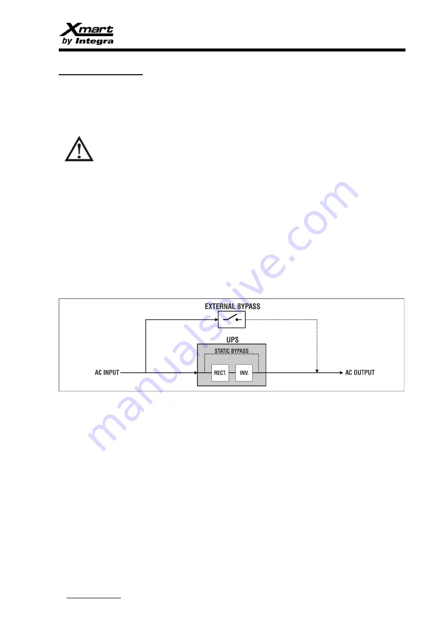
From time to time, all UPS require some kind of maintenance that can only be performed if UPS is powered-off. In that case, an external 

maintenance bypass switch is actuated to keep system running by feeding it from the AC input service even UPS is powered-off. 


OPTIMA tower 6K and 10K have their own MBS switch located on rear panel. 


OPTIMA RT 6K and 10K require an external MBS switch. XMART can provide as an option MBS accessory named MBS-10K-TB 


BEFORE ACTIVATING ANY KIND OF EXTERNAL BYPASS SWITCH, UPS MUST BE SET IN INTERNAL STATIC BYPASS 

MODE. IF NOT INVERTER OUTPUT OF THE UPS WILL BE SHORTED WITH AC MAIN INPUT. THAT SITUATION COULD 

PRODUCE PERMANENT DAMAGE IN THE UPS. 


MBS located on rear panel of OPTIMA tower models has a safety plate. As soon as this plate is removed, UPS adopts static bypass 

mode to prepare UPS to the imminent external BYPASS activation.  

For RT models, the XMART MBS-10K-TB external accessory also has this safety plate and a related status signal cable to allow 

OPTIMA RT UPS to know when safety plate is removed. 


IMPORTANT:  

Standard RT9W model does not has status port for safety plate detection so operator MUST change UPS to static bypass mode before 

actuating external bypass switch. 

Meanwhile UPS in under maintenance bypass mode, load is powered by AC input service so any problem in main service will affect directly 

to the load. 


GENERIC EXTERNAL BYPASS SWITCH: 

In case user decides to install a generic external bypass switch without a safety plate status 

signal, the operator will be responsible of setting UPS in static bypass mode before actuating the external switch. 

External bypass switch are usually installed according to below figure: 


PROCEDURE FOR ACTIVATING EXTERNAL BYPASS 

1)


Confirm bypass mode is allowed in UPS configuration. Check input voltage is in the acceptable input range for bypass mode. 

2)


Set UPS in static bypass mode by pressing OFF button in front panel. Ups will adopt bypass mode only in bypass is allowed by 

configuration and input is inside bypass range. Check bypass LED in front panel is ON and online LED is OFF.  

3)


Activate External BYPASS switch to bypass position to connect AC input directly to the load. 

4)


Once the load is powered by AC main input service, UPS can be powered off for maintenance. If there are external batteries, 

proceed to open DC switches on XBAT to disconnect batteries from the UPS. 


COMING BACK FROM MAINTENANCE BYPASS MODE TO NORMAL MODE 

With system in maintenance bypass mode (Input lines open and UPS powered-off): 


1)


Power AC input lines and switch-ON input breaker located on rear panel of UPS. If UPS has external batteries, connect them to 

the UPS switching-on DC switches on XBAT rear panels. 

2)


Verify UPS enters in static bypass mode. Bypass LED must be ON and online LED must be OFF 

3)


Actuate external bypass switch to OFF state (open). In case of using a XMART MBS, set it to BYPASS position and re-install its 

safety plate. 

4)


At this moment load is feed by UPS output in static bypass mode.  

5)


Turn UPS on by pressing ON button on front panel. Keep ON button pressed during 2s or longer. 


Summary of Contents for Xmart ISOTX-06K-OPT-RACK-UL

Page 1: ...L www xmart ups com VER 2106 21 One ENG 1 VER 21 06 21 ENGLISH USER MANUAL OPTIMA RT10 6K 10K UL UPS ONLINE DOUBLE CONVERSION RACK TOWER INSTALLATION OPTIMA RT10 06K 230 UL OPTIMA RT10 10K 230 UL ISOTX 06K OPT RACK UL ISOTX 10K OPT RACK UL ...

Page 2: ...ed or distributed totally or partially without written approval of XMART XMART can introduce modifications in their products or manuals without further notice XMART is not responsible of mistakes or missing information in this manual XMART is not responsible for wrong use a third part can do of this information Trademarks and logos in this manual are property of their owners ...

Page 3: ... 3 PRODUCT DESCRIPTION 4 INSTALLATION INSTALLATION INDIVIDUAL UPS INSTALLATION PARALLEL UPS 5 OPERATION MODES 6 OPERATION INTERFACE KEYBOARD LCD 7 UPS CONFIGURATION 8 START UP INDIVIDUAL UPS PARALLEL UPS 9 ERROR ALARMS CODES TROUBLESHOOTING 10 SOFTWARE 11 BATTERIES MAINTENANCE 12 BATTERIES CHARGER CONFIGURATION SERVICE 13 SUPPORT WARRANTY 14 REAR PANEL 15 SPECIFICATIONS ...

Page 4: ...s Bracelets etc because they could contact conductive parts and components inside the UPS and this might cause discharges and or short circuits Make sure using tools properly isolated to avoid electrical risks WARNING This product has been designed to be used indoors protected from water direct sun light dust and extreme temperature WARNING Do not put any object on the UPS do not apply any force o...

Page 5: ...ATION IEC EN 300019 2 2 Class 2 3 WARNING Modifications made on the product or the use of this product as a part of a more complex system not expressly approved by the party responsible for compliance could void the user s authority to operate the equipment It also could affect its performance and the compliance of regulations XMART is not responsible of modifications made after manufacturing WARN...

Page 6: ...controlling this UPS by any of available communications ports USB RS232 or LAN Ethernet optional card under SNMP protocol This model can be installed in both tower format and inside 19 rack cabinets Rack installation requires some mounting accessories not included with the product This UPS comes with 2 main modules 1 UPS Module This module contains electronic and power parts It operates with 220 2...

Page 7: ... electrical shock because high DC voltage External battery banks must be revised before connecting them to UPS to confirm their DC voltage is compatible with this UPS DC polarity of the Battery bank must be revised to confirm it is OK before connection A reverse polarity can generate permanent damage in batteries and UPS This UPS is rated as Class I so it is recommendable to connect GROUND termina...

Page 8: ... to find voltage in input lines of the UPS so that a backfeed failure could represent an electrical shock risk for the operator An effective backfeed design must be able to open automatically all UPS AC input lines when AC main is power off External Backfeed protection device is not included with this product In below figure a typical automatic backfeed protection design is described C 2 Poles Con...

Page 9: ... never rise over 35 ºC Batteries life shortens over 25 ºC Installation site must be dry fresh free of dust fibers and any other objects conductors or not suspended in the air that could get into the UPS thru the ventilation system Fan Do not block UPS ventilations UPS INPUT AND OUTPUT POWER LINES PROTECTION AC LINES PROTECTIONS DEVICES All UPS Inputs and outputs must be protected by circuit breake...

Page 10: ...abinet 19 RACK MOUNTING Rack UPS must be installed using L Shape type guides for supporting UPS weight Usually this kind of supports is provided with rack cabinets If not UPS distributor can provide original XMART telescopic guides as optional accessory Small black handles included with the UPS are only for locking purposes UPS cannot be supported only by these handles ...

Page 11: ...L OPTIMA RT10 6K 10K UL www xmart ups com VER 2106 21 One ENG 11 VERTICAL MOUNTING UPS can be installed in vertical format by using plastic supports Fig 1 2 These supports are included inside the box 2 MODULES UPS XBAT ...

Page 12: ...INDEX USER MANUAL OPTIMA RT10 6K 10K UL www xmart ups com VER 2106 21 One ENG 12 3 MODULES UPS XBART OPTIONAL ISOTX ...

Page 13: ...ll OPTIMA RT 6K and 10K work with 240VDC battery voltage This voltage is provided by battery packs by connecting 20 batteries 12VDC in series There could be some UPS models working with a different DC voltage User must check carefully XBAT voltage is compatible with the UPS DC voltage before making DC connections In case electrical information given by this manual does match with information provi...

Page 14: ...OUTPUT 1 x 120Vac N1 100 Watts SEPARE OUTPUTS 2 x 120Vac N2 50 Watts C U 6KVA with ISOTX Output 110 220V Unique Output Capacity 6000VA 6000W Output Voltage 120Vac AC Breaker 80A Curve D Max Nominal Current 70A Wiring min size 6AWG 16 mm2 VA W per Output 3000VA 3000W Output Voltage 120Vac AC Breaker 40A Curve D Max Nominal Current 36A Wiring min size 10AWG 6 mm2 10KVA with ISOTX Output 110 220V Uni...

Page 15: ... not powered including external batteries UPS XBAT UPS with 220V output generated by UPS inverter This product has 2 basic modules UPS Batteries This UPS can be feed with 220V 240V line L N to generate one output with a configurable value 208 220 230 or 240Vac UPS module is connected to XBAT module by using original XMART DC cable AC TERMINAL BLOCK ON UPS Remove TB cover plate located on rear pane...

Page 16: ...SER MANUAL OPTIMA RT10 6K 10K UL www xmart ups com VER 2106 21 One ENG 16 ISOTX OPTIONAL MODULE ISOTX module is an optional accessory not included with the UPS It provides 2 galvanic isolated outputs 120V each ...

Page 17: ...VER 2106 21 One ENG 17 AC TERMINAL BLOCK CONNECTION BETWEEN UPS AND ISOTX UPS 240Vac output is connected to ISOTX input ISOTX input generates 2 outputs of 120V These 2 outputs can be wired as indicated in next section of this manual ISOTX OUTPUT CONFIGURATION ...

Page 18: ...nfigurations according to below wiring diagrams 2 individual outputs 120V 50 of UPS capacity each 1 output 120V 100 of UPS capacity 1 output 240V 100 of UPS capacity UPS output can be configured in the front panel LCD of the UPS as 208 220 230 or 240V ISOTX transformation ratio is 2 1 so 120V outputs will be half the voltage of output configured in the UPS ...

Page 19: ...arallel connection also allows system can grow in power by adding extra units For working parallel as a parallel system all units must share same AC input and AC output Some control cables must be also connected between units of the system so that UPS will be able to know important information to share the load efficiently All input and output lines must have their own breakers one per UPS for saf...

Page 20: ...mmendable all output neutral lines are connected directly without breakers It is important neutral lines are connected always since neutral is an important electrical reference for all UPS of the parallel system In battery mode the lack of connection of output neutrals could generate synchronization errors between UPS In case neutral lines are connected through breakers there is a possibility of a...

Page 21: ...PS must be connected following same principle IMPORTANT It is recommendable all output neutral lines are connected directly without breakers It is important neutral lines are connected always since neutral is an important electrical reference for all UPS of the parallel system In battery mode the lack of connection of output neutrals could generate synchronization errors between UPS In case neutra...

Page 22: ... It is recommendable all output neutral lines are connected directly without breakers It is important neutral lines are connected always since neutral is an important electrical reference for all UPS of the parallel system In battery mode the lack of connection of output neutrals could generate synchronization errors between UPS In case neutral lines are connected through breakers there is a possi...

Page 23: ...S must be connected following same principle IMPORTANT It is recommendable all output neutral lines are connected directly without breakers It is important neutral lines are connected always since neutral is an important electrical reference for all UPS of the parallel system In battery mode the lack of connection of output neutrals could generate synchronization errors between UPS In case neutral...

Page 24: ... 21 One ENG 24 CONTROL CABLES CONNECTION DIAGRAM Parallel system requires all UPS share some important control information by parallel control cables There are 2 kind of control cables SHARED CURRENT PARALLEL CONTROL They must be connected as indicated in below figure ...

Page 25: ...nput on its terminals If bypass mode is not enable UPS will simply lights its LCD Outputs will keep powered off 2 Bypass mode is adopted as soon as a problem is detected in its internal circuitries 3 Bypass mode is also activated in case an external overload is detected in UPS output It happens when equipment connected to UPS output requires a power higher than max power of the UPS MAINTENANCE BYP...

Page 26: ...SS SWITCH In case user decides to install a generic external bypass switch without a safety plate status signal the operator will be responsible of setting UPS in static bypass mode before actuating the external switch External bypass switch are usually installed according to below figure PROCEDURE FOR ACTIVATING EXTERNAL BYPASS 1 Confirm bypass mode is allowed in UPS configuration Check input vol...

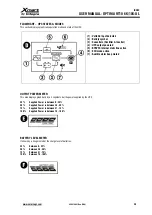
Page 27: ...s generated by inverter BATTERY MODE A Input indicator at bottom left corner A shows Battery voltage since there is no valid AC input detected B Output indicator displays AC output generated by UPS inverter C AC input symbol must be turned off representing there is no valid AC input detected by UPS D Clock symbol lights and backup time is displayed on the screen BYPASS MODE A Input and output indi...

Page 28: ...s release before required time UPS will not turn on ENTER When UPS is in configuration mode this key operates as ENTER OFF ESCAPE UPS TURN OFF Press during 2 seconds to turn UPS off SCAPE When UPS is in configuration mode this key operates as SCAPE TEST UP BATTERY TEST Operator can manually initiate a Battery test when UPS is ONLINE if this key is selected UP When UPS is in configuration mode this...

Page 29: ...T INFORMATION It displays AC output voltage Output frequency in Hz ALARMS ERRORS This section of the LCD displays active alarms and errors providing codes and descriptive symbols This section also shows remaining runtime in battery mode 1 2 UPS Runtime 2 3 Alarm error code 2 Menu ID in CONFIGURATION mode 4 Not used in this model 5 Battery fault active 6 Battery low level 7 Output Overload detected...

Page 30: ...ed 5 BYAPSS internal static line active 6 ECO mode active 7 Audible alarm beep muted OUTPUT POWER METER This area displays graphically by a 4 segments bar the power supplied by the UPS 25 Supplied Power is between 0 25 50 Supplied Power is between 26 50 75 Supplied Power is between 51 75 100 Supplied Power is between 76 100 BATTERY LEVEL METER It shows by a 4 segments bar the charge level of batte...

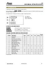
Page 31: ... UP Used as key to navigate or changing parameters value ON ENTER Used as ENTER key to confirm modifications MUTE DOWN Used as key to navigate or changing parameters value AVAILABLE FUNCTIONS UNDER EACH OPERATION MODE FUNTION DESCRIPTION Bypass Normal ECO CVCF Battery Battery Test 1 Output Voltage 2 CF function 3 Input voltage range for BYPASS 4 Input frequency range for BYPASS 5 ECO Enable Disabl...

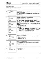
Page 32: ...alue of input frequency If ATO is selected output frequency will be set by input frequency read when UPS started by first time from 46 to 54 Hz will set to 50Hz from 56 to 64 Hz will set to 60Hz IMPORTANT 1 If CF is active output power is decreased by 30 It means max UPS power will be 70 of max rated power Example a 10KVA only will be able to supply 7KVA max 2 BYPASS mode is automatically prohibit...

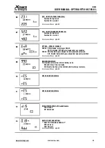
Page 33: ...wed under any condition PAR 03 ENA Enable Bypass allowed in both manual and automatic DIS Disable Automatic Bypass allowed but manual is prohibited Set values with keys 09 MAXIMUM RUNTIME This function sets maximum time in Battery mode 000 a 999 Max Time in minutes DIS Disable Runtime will be limited by Battery charge level only Set values with keys 10 NOT USED IN THIS MODEL 11 NOT USED IN THIS MO...

Page 34: ...s to configure the current value 1A 2A 3A o 4A PAR 3 Allows calibration of current in case there is a difference between configured value and real value measured Set values with keys LCD CODES AND TEXTS TEXT DESCRIPTION BAT Battery Batería CF Frequency Converter Function Enable Función de Convertidor de Frecuencia Activado NCF Frequency Converter Function Disable Función de Convertidor de Frecuenc...

Page 35: ...Power input lines ON at electrical board by setting Circuit Breaker to ON 3 Put Battery Bank breaker to ON in case UPS has XBAT connected 4 Put AC INPUT Breaker to ON in UPS rear panel 5 LCD of UPS must turns on UPS should adopt bypass mode 6 Start up the UPS by pressing ON push button during a couple of seconds ON button must be pressed until LCD shows the text ON If ON button is released before ...

Page 36: ...PARALLEL UPS Check all previous requirements are complied If not do nott try to start ups parallel UPS 1 Check parallel UPS are powered OFF and turned OFF 2 Check all input breakers are in OFF position 3 Power all AC input lines 4 Check external batteries are connected to UPS Switch DC breakers to ON position for all XBAT 5 Switch input breaker to ON position in UPS 1 Wait until UPS complete its a...

Page 37: ...ttery backup of remaining UPS could not be enough to keep system running before reconnecting removed unit External breakers could be activated randomly during operation so system could be tripped 3 There must be a detailed plan to perform this procedure identifying all maintenance activities to be performed on removed unit before reconnecting it 4 Remaining UPS must be able to support the power sy...

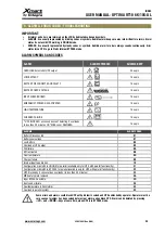
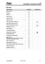
Page 38: ...s CHARGER FAILURE 1 beep s UPS BLOCKED as consequence of detecting 3 overloads in less than 30 minutes OR MBS cover REMOVED 1 beep s ALARMS ALARM CODES Battery Disconnected 01 Battery overvoltage 07 Los Battery 08 Overload at UPS output 09 FAN failure 0A EPO activated 0B Over temperature 0D Charger failure 0E Internal input fuse broken 10 Configuration mismatch in ONLINE for parallel available onl...

Page 39: ...ery SCR 21 SHORT CIRCUIT detected at inverter output 24 COMMUNICATION CAN error 31 OVER TEMPERATURE 41 CPU COMMUNICATION ERROR 42 OVERLOAD Detected at UPS output 43 OVERCURRENT IN INVERTER 60 OVERTEMPERATURE IN TRANSFORMER 77 NEGATIVE OUTPUT External device is injecting current to the UPS from its output 1A SHORT CIRCUIT detected at Battery charger 2A BATTERY PROBLEM Start up 6A RECTIFIER PROBLEM ...

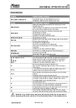
Page 40: ...E SOLUCION 01 02 03 04 11 12 13 24 6A 6B 6C 60 63 Turn off and power off UPS Disconnect all equipment connected to UPS Restart UPS with no loads connected to its output If UPS starts up without problems find faulty equipment and remove it from UPS If problem is not solved call technical support 14 Short circuit detected in the load connected to UPS Turns UPS OFF Identify faulty load and remove it ...

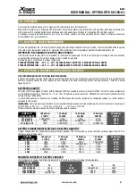
Page 41: ...nology VRLA and specifications 12VDC and similar capacity in AH BATTERIES QUANTITY This type of UPS is equipped at factory with 20 batteries 12VDC connected in serial for a total of 240VDC This UPS can be configured to work with different quantity of batteries 16 17 18 19 or 20 batteries in serial connection HOWEVER it is not recommendable to modify factory setting of 20 batteries In case battery ...

Page 42: ...ution service partners reserve the right to charge handling fee if returned product is free of failure or it is out of warranty because any of the reasons described in this warranty 6 If product is out of warranty a reparation proposal will be sent to the user for his approval If proposal is not accepted service center will keep product available for the user during 60 continuous days After this p...

Page 43: ...om ISOTX 9 Parallel Control Ports Shared Current 3 AC Input Breaker 10 Parallel Control Ports Parallel Control 4 Connector for Ext Bypass status signal 11 Temperature Port ISOTX 5 DC connector for external batteries 12 Fan ISOTX 6 Intelligent port 13 AC Input ISOTX 7 USB RS232 14 AC Output ISOTX RS232 COMMUNICATION PORT Serial communication port Pinout Pin 2 RX Pin 3 TX Pin 5 GND ...

Page 44: ...nte de Entrada Starting Time Tiempo de Arranque 100 130 only warning 130 1min Comply to IEC 62040 3 Class 1 Comply to IEC 62040 3 Class 1 100ms IEC 62040 3 ref Non linear load RT10 6KVA 230 RT10 10KVA 230 6000VA 6 000W 10000VA 10 000W Rated Input Entrada Nominal 208 220 230 240 Vac single phase L N G 110Vac 300Vac 0 60 load 140Vac 300Vac 61 80 load 176Vac 300Vac 81 100 load 40 70 Hz 30A RMS 50A RM...

Page 45: ... salida se reduce en 1 cada 100m sobre los 1 000msnm Note 4 Bypass mode is prohibited automatically when CF function is activated El modo bypass se anula automaticamente cuando se activa la función CF N5 Recharing time based on previous 10min to 20min full discharging cycles Tiempo de recarga basado en ciclos previos de descarga profunda de 10 a 20min 97 AS400 optional interface board Interfaz AS4...

Page 46: ...INDEX USER MANUAL OPTIMA RT10 6K 10K UL www xmart ups com VER 2106 21 One ENG 46 NOTAS ...

Page 47: ......

Page 48: ...USA Main Offices Doral FL 33172 USA EUROPE Main Offices Sabadell 08202 Spain Latin America Main Offices Santiago de Chile Chile ...

Reviews: