background image


85


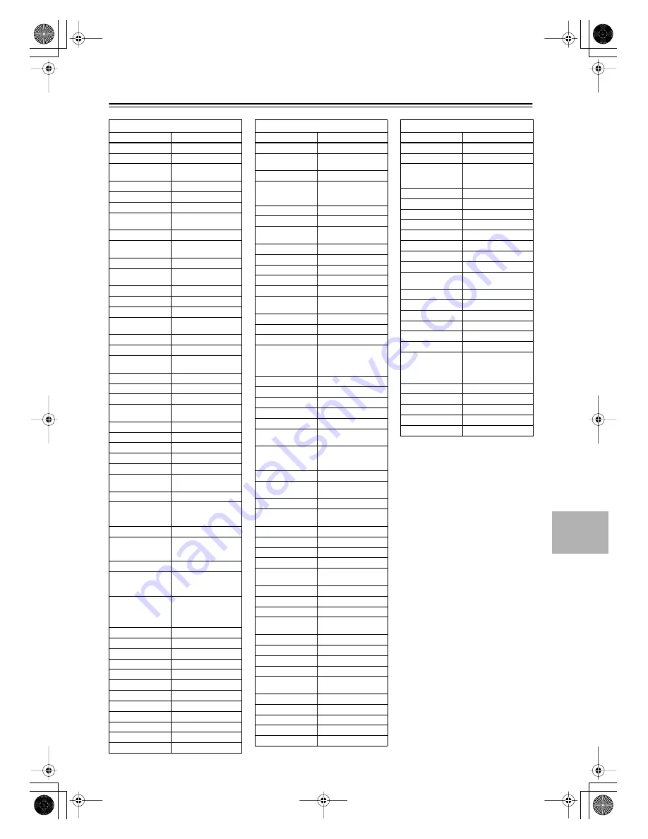
Controlling Other Components


—Continued


TV


Manufacturer

Control code


Loewe

1014, 1040, 1055

Luxman

1004, 1006

LXI

1001, 1006, 1010, 1014, 
1016, 1017, 1034

M Electronic

1035, 1053, 1062, 1063

Magnadyne

1040, 1067, 1068

Magnafon

1067

Magnavox

1004, 1006, 1008, 1014, 
1018, 1020

Marantz

1004, 1006, 1014, 1060

Matsui

1035, 1043, 1048, 1050, 
1063, 1064, 1067, 1068

Megatron

1006

Memorex

1005, 1006, 1010, 1017, 
1035

Metz

1040, 1051, 1058

MGA

1004, 1005, 1006, 1008

Minerva

1039, 1058, 1059, 1064

Mitsubishi

1004, 1005, 1006, 1008, 
1040, 1055, 1058

Mivar

1047, 1056, 1067

Motorola

1003, 1026

MTC

1004, 1005, 1006, 1022, 
1055

Multitech

1009, 1035

NAD

1006, 1016

NEC

1003, 1004, 1005, 1006

Neckermann

1040, 1041, 1054, 1059, 
1060

Nikkai

1045

Nikko

1006

Oceanic

1062

Onwa

1009

Optonica

1021, 1026

Orion

1029, 1043, 1048, 1049, 
1050, 1067, 1068

Osaki

1045, 1063

Otto Versand

1036, 1041, 1043, 1054, 
1055, 1058, 1059, 1060, 
1063

Palladium

1052

Panasonic

1003, 1012, 1014, 1031, 
1044, 1046, 1051, 1061, 
1062, 1069

Pathe Marconi

1066

Philco

1003, 1004, 1005, 1006, 
1007, 1008, 1014, 1018, 
1040

Philips

1003, 1004, 1007, 1008, 
1014, 1018, 1019, 1020, 
1037, 1038, 1040, 1053, 
1059, 1060

Phoenix

1040

Phonola

1037, 1040

Pioneer

1004, 1006, 1027, 1062

Portland

1004, 1005, 1006, 1025

Price Club

1022

Prism

1012

Profex

1035

Proline

1049

Proscan

1001, 1034

Protech

1035, 1045, 1063

Proton

1004, 1006, 1007

Pye

1037

Quasar

1003, 1012, 1031

Quelle

1036, 1039, 1054, 1055, 
1058, 1059, 1068

Radio Shack

1010, 1017, 1034

Radio Shack/
Realistic

1001, 1004, 1006, 1007, 
1009, 1010, 1017, 1021, 
1025

Radiola

1037

Radiomarelli

1040, 1067

RCA

1001, 1003, 1004, 1005, 
1006, 1008, 1027, 1034

Realistic

1010, 1017, 1034

Rex

1045, 1062

RFT

1040

Roadstar

1035, 1045

Saba

1040, 1062, 1066, 1069

Saisho

1035, 1043, 1045, 1067, 
1068

Salora

1062

Sambers

1056, 1067

Sampo

1004, 1006, 1025

Samsung

1004, 1005, 1006, 1007, 
1008, 1022, 1025, 1035, 
1045, 1047, 1052, 1056, 
1060, 1063, 1065

Sansui

1029

Sanyo

1004, 1010, 1017

SBR

1037, 1038

Schaub Lorenz

1069

Schneider

1068

Scott

1004, 1006, 1007, 1009, 
1070

Sears

1001, 1004, 1006, 1008, 
1010, 1015, 1016, 1017, 
1028, 1034, 1070

SEG

1045, 1063

SEI

1036, 1040, 1048, 1067, 
1068

Seleco

1062

Sharp

1004, 1006, 1007, 1021, 
1023, 1025, 1026

Shorai

1048

Siarem

1040, 1067

Siemens

1041, 1042, 1058, 1059

Singer

1040

Sinudyne

1036, 1040, 1043, 1067, 
1068

Solavox

1062

Sonoko

1035

Sonolor

1062

Sony

1002, 1030, 1032, 1036, 
1054

Soundesign

1004, 1006, 1009, 1070

Starlite

1009

Stern

1062

Sunkai

1043, 1048, 1049, 1050

Sylvania

1004, 1006, 1008, 1014, 
1018, 1020

Symphonic

1009, 1028

Tandy

1026, 1062, 1063

Tashiko

1038, 1063

Tatung

1003, 1063, 1067

Tec

1063


TV


Manufacturer

Control code


Technics

1012, 1044, 1061

Techwood

1004, 1006, 1012

Teknika

1004, 1005, 1006, 1007, 
1009, 1022, 1025, 1031, 
1070

Teleavia

1066

Telecaption

1024

Telefunken

1066

Teletech

1035

Teleton

1063

Tensai

1048

Thomson

1066

Thorn

1054, 1055, 1058

Toshiba

1010, 1016, 1017, 1022, 
1024, 1039

Totevision

1025

Triumph

1067

Universal

1011, 1019

Universum

1045, 1052, 1058

Voxson

1040, 1062

Waltham

1063

Wards

1001, 1004, 1005, 1006, 
1008, 1011, 1014, 1018, 
1019, 1020, 1021, 1034, 
1070

Watt Radio

1068

Wega

1040

Yamaha

1004, 1005, 1006, 1008

Yoko

1045, 1063

Zenith

1004


TV


Manufacturer

Control code

DTR-6.5,5.5̲En.book Page 85 Wednesday, July 28, 2004 9:07 AM

Summary of Contents for DTR-5.5

Page 1: ...DTR 6 5 5 5 Instruction Manual AV Receiver DTR 6 5 5 5 En book Page 1 Wednesday July 28 2004 9 07 AM...

Page 2: ...lly by following the operating instructions Adjust only those controls that are covered by the operating instructions as an improper adjustment of other controls may result in damage and will often re...

Page 3: ...ug CAUTION TO PREVENT ELECTRIC SHOCK MATCH WIDE BLADE OF PLUG TO WIDE SLOT FULLY INSERT Mod le pour les Canadien REMARQUE CET APPAREIL NUM RIQUE DE LA CLASSE B EST CONFORME LA NORME NMB 003 DU CANADA...

Page 4: ...ropean Models Supplied Accessories Make sure you have the following accessories In catalogs and on packaging the letter at the end of the product name indicates the color Specifications and operation...

Page 5: ...rating Audio Video CinemaFILTER 5 Subwoofer pre out 6 digital inputs 4 optical 2 coaxial 1 digital optical output DTR 6 5 5 5 1 Manufactured under license from Dolby Laboratories Dolby Pro Logic Surro...

Page 6: ...s of Other Components 38 Connecting the Supplied Power Cord 38 Turning On the AV receiver 38 First Time Setup Automatic Speaker Setup 39 About the Onscreen Setup Menus 41 Initial Setup 42 Digital Inpu...

Page 7: ...sing the Re EQ Function DTR 6 5 only 62 Using the CinemaFILTER TDR 5 5 only 62 Adjusting Individual Speaker Levels 63 Using the DVD Analog Multichannel Input 63 Recording 64 Zone 2 Connecting Zone 2 7...

Page 8: ...nels Front Panel Standby Zone 2 1 Z Y W V U X 56 789 J K M N Q T S O P R L 234 Standby Zone 2 1 Z Y W V U X 5678 J K L N O R T P Q S M 234 9 DTR 6 5 DTR 5 5 DTR 6 5 5 5 En book Page 8 Wednesday July 2...

Page 9: ...button 56 This button is used to select the Auto or Manual tun ing mode P Dimmer button 54 This button is used to adjust the display brightness Q Setup button 42 This button is used to access the ons...

Page 10: ...ng radio stations FM STEREO This indicator lights up when the AV receiver is tuned to a stereo FM station 6 SLEEP indicator 54 This indicator lights up when the Sleep function has been set 7 Message a...

Page 11: ...er s A BUS RI45 Hub to an A BUS keypad Warning DO NOT connect A BUS output to any computer or network connections i e ethernet it will cause damage to the computer or network components as 24 volt pow...

Page 12: ...with an analog audio input and output cassette Mini Disc etc S VIDEO 3 IN 27 31 Here you can connect a video source VCR set top box etc Input jacks include S Video composite video and analog audio T...

Page 13: ...e type is used in the same room or the AV receiver is installed close to equipment that uses infrared rays the remote control ler may not work reliably Don t put anything such as a book on the remote...

Page 14: ...Mode button Receiver Mode Pure A On Standby TV Display Muting Random Rec Last Memory Angle Subtitle Audio Memory Search A B Repeat RC 585M Exit Guide Prev CH TV CH TV VOL Dimmer Tape TV Input Sleep In...

Page 15: ...listening mode Pure A button This button is used to select the Pure Audio listen ing mode Direct button This button is used to select the Direct listening mode DSP DSP buttons These buttons are used t...

Page 16: ...me total time and so on I Playback buttons From left to right Previous Play Next Fast Reverse Pause Stop and Fast Forward J Step Slow buttons These buttons are used for frame by frame playback and slo...

Page 17: ...f titles chapters or tracks CD mode is used to control an Integra CD player con nected to the AV receiver via To set the remote controller to CD mode press the CD Remote Mode button 1 On button This b...

Page 18: ...on This button is used to pause playback G Rec button This button is used to start recording H Repeat button This button is used to set the repeat playback func tions I Open Close button This button i...

Page 19: ...his button is used to start playback 2 Previous Next buttons The Previous button is used to select the pre vious track During playback it selects the begin ning of the current track The Next button is...

Page 20: ...your subwoofer will depend on its posi tion the shape of your listening room and your listening position In general a good bass sound can be obtained by installing the subwoofer in a front corner or...

Page 21: ...Jack Description Component video cable Component video separates the luminance Y and color difference signals PR PB providing the best picture quality Some TV manufacturers label their component vide...

Page 22: ...nnect the SUB WOOFER PRE OUT to an input on the amp Attaching the Speaker Labels The AV receiver s positive speaker terminals are color coded for ease of identification The negative speaker terminals...

Page 23: ...tive terminals to only positive terminals and negative terminals to only nega tive terminals If you get them the wrong way around the sound will be out of phase and will sound unnatural Unnecessarily...

Page 24: ...e yourself when using thumbtacks R L R L FRONT SPEAKERS CENTER SPEAKER R L R L R L SURROUND BACK SPEAKERS SURROUND SPEAKERS IN 1 IN 2 IN 3 FRONT SURR CENTER FRONT SURR CENTER SURR BACK DVD CD VIDEO 3...

Page 25: ...nce with local regulations to prevent electrical shock haz ards Using a TV FM Antenna Splitter It s best not to use the same antenna for both FM and TV reception as this can cause interference problem...

Page 26: ...OUT V and S jacks Note The DTR 6 5 5 5 can be set to upconvert com posite video and S Video input signals and output them from the COMPONENT VIDEO OUT see page 43 Audio Connection Formats Audio equip...

Page 27: ...3 IN4 OUT COAXIAL DIGITAL RS232 R L PHONO IN GND MONITOR OUT V VIDEO IN TV projector etc R L IN 1 IN 2 IN 3 FRONT SURR CENTER FRONT SURR CENTER SURR BACK DVD CD VIDEO 3 VIDEO 2 VIDEO 1 VIDEO 3 VIDEO 2...

Page 28: ...COMPONENT VIDEO PB Y PR IN OUT IN IN IN OUT R L R L REMOTE CONTROL ZONE 2 OUT V S IN 1 IN 2 OUT OPTICAL IN1 IN2 IN3 IN4 OUT COAXIAL DIGITAL RS232 R L PHONO IN GND VIDEO OUT IN DVD DVD player R L IN 1...

Page 29: ...1 channel analog audio output on your DVD player as shown Alterna tively use several analog audio cables R L IN 1 IN 2 IN 3 FRONT SURR CENTER FRONT SURR CENTER SURR BACK DVD CD VIDEO 3 VIDEO 2 VIDEO...

Page 30: ...ng a VCR for Playback R L IN 1 IN 2 IN 3 FRONT SURR CENTER FRONT SURR CENTER SURR BACK DVD CD VIDEO 3 VIDEO 2 VIDEO 1 VIDEO 3 VIDEO 2 PRE OUT VIDEO 1 IN IN IN OUT OUT IN IN OUT OUT TAPE SUB WOOFER SUB...

Page 31: ...ut on the recording VCR Notes The AV receiver must be turned on for recording Recording is not possible while it s in Standby mode If you want to record directly from your TV or play back VCR to the r...

Page 32: ...Y PR IN OUT IN IN IN OUT R L R L REMOTE CONTROL ZONE 2 OUT V S IN 1 IN 2 OUT OPTICAL IN1 IN2 IN3 IN4 OUT COAXIAL DIGITAL RS232 R L PHONO IN GND VIDEO OUT IN VIDEO 3 Satellite cable set top box LD pla...

Page 33: ...ks to the analog audio output on your camcorder games console etc as shown If your camcorder games console etc has an optical digital audio output use an optical digital audio cable to connect it to t...

Page 34: ...UB WOOFER MONITOR OUT DVD COMPONENT VIDEO PB Y PR IN OUT IN IN IN OUT R L R L REMOTE CONTROL ZONE 2 OUT V S IN 1 IN 2 OUT OPTICAL IN1 IN2 IN3 IN4 OUT COAXIAL DIGITAL RS232 R L PHONO IN GND OPTICAL IN...

Page 35: ...igital outputs Doing so may create a signal loop and cause a malfunction R L IN 1 IN 2 IN 3 FRONT SURR CENTER FRONT SURR CENTER SURR BACK DVD CD VIDEO 3 VIDEO 2 VIDEO 1 VIDEO 3 VIDEO 2 PRE OUT VIDEO 1...

Page 36: ...s shown Connecting a Turntable R L IN 1 IN 2 IN 3 FRONT SURR CENTER FRONT SURR CENTER SURR BACK DVD CD VIDEO 3 VIDEO 2 VIDEO 1 VIDEO 3 VIDEO 2 PRE OUT VIDEO 1 IN IN IN OUT OUT IN IN OUT OUT TAPE SUB W...

Page 37: ...omponents have two jacks You can connect either one to this AV receiver The other jack is for connecting more compatible components Connect the AV receiver s jack to only IntegraAV components Connecti...

Page 38: ...ct the power cord from the AV receiver while the other end is still plugged into a wall outlet Doing so may cause an electric shock Always discon nect the power cord from the wall outlet first Notes P...

Page 39: ...DR Input Selector V1 V2 V3 CD Phono Tape V4 DVD Multi CH Tuner Remote Mode Zone 2 3 7 Standby Zone 2 2 1 2 Put the speaker setup micro phone in the listening position and connect it to the Setup Mic j...

Page 40: ...Enter Enter Press the Return button to return to the previous menu Menus vary depending on country When a speaker has a warning its abbre viation e g L R and so on appears instead of the dashes If you...

Page 41: ...de Preset 6 Preference Basic Setup 1 Initial Setup 2 Component Video 3 Hardware Setup 1 Digital Input 2 Speaker Setup 2 Speaker Distance 3 Level Calibration 4 Equalizer Settings 1 Speaker Config 3 Dec...

Page 42: ...ode Zone 2 2 4 2 3 1 5 1 Receiver Enter Enter 3 Use the Up and Down buttons to select 1 Digital Input and then press Enter The Digital Input menu appears There are no assignments for TUNER VIDEO 4 is...

Page 43: ...on fol lowed by the Setup button The main menu appears onscreen 2 Use the Up and Down buttons to select 1 Initial Setup and then press Enter The initial Setup menu appears 3 Use the Up and Down button...

Page 44: ...Off Open Close Macro 1 2 3 MD CDR Re EQ Input Selector V1 V2 V3 CD Phono Tape V4 DVD Multi CH Tuner Remote Mode Zone 2 2 4 1 5 2 3 1 Receiver 2 Use the Up and Down buttons to select 1 Initial Setup a...

Page 45: ...enu appears Menus vary depending on country 4 Use the Up and Down buttons to select c TV Format and then use the Left and Right buttons to select Auto Conforms with the video input signal PAL Select i...

Page 46: ...iver CD 10 0 Clear 7 8 9 Macro 1 2 3 MD CDR Input Selector CD Phono Tape Tuner Remote Mode Zone 2 1 12 2 11 2 3 1 Receiver 2 Use the Up and Down buttons to select 2 Speaker Setup and then press Enter...

Page 47: ...k speakers are large None Select if no surround back speakers are connected Notes If the Surround setting in step 7 is set to None this setting cannot be selected If the Surround setting in step 7 is...

Page 48: ...tons to select On Double Bass function on Off Double Bass function off default 12 Press the Setup button The setup menu closes This setting is not set automatically by the Automatic Speaker Setup func...

Page 49: ...set to No or None on the Speaker Configuration page page 46 cannot be selected 4 Use the Up and Down buttons to select a Unit and then use the Left and Right buttons to select feet Select if you want...

Page 50: ...ut Sleep Enter Top Menu Menu Setup Return VOL CH Disc SAT TV VCR Cable DVD Receiver CD 10 0 Clear 7 8 9 Macro 1 2 3 MD CDR Input Selector CD Phono Tape Tuner Remote Mode Zone 2 1 6 2 4 2 3 1 Receiver...

Page 51: ...e 3 Level Calibration 4 Equalizer Settings 1 Speaker Config Enter Enter 4 Use the Left and Right buttons to select Off Tone off response flat Auto The tone for each speaker is set automatically by the...

Page 52: ...etting can only be changed on the AV receiver Changing the TAPE MD CDR Display 1 Press the TAPE input selector button so that TAPE appears on the display 2 Press and hold down the TAPE input selector...

Page 53: ...ons On the remote controller the V1 V2 V3 and V4 buttons select the VIDEO 1 VIDEO 2 VIDEO 3 and VIDEO 4 input sources respectively Only the RC 585M remote controller has a PHONO button 2 Start playbac...

Page 54: ...l input is used only the front left and right audio can be heard in the headphones On the DTR 6 5 when the Stereo or Mono listening mode is selected audio is downmixed for a good sound Setting the Dis...

Page 55: ...eans front left front right and center B The number of surround channels 2 means surround left and surround right If there s surround back channel information this will be 3 C LFE channel for subwoofe...

Page 56: ...from a stereo FM station is weak it may be impossible to get good reception In this case switch to Manual Tuning mode and listen to the station in mono Using the Tuner 1 Use the TUNER input selector b...

Page 57: ...store the station The station is stored and the preset number stops flashing Repeat this procedure for all your favorite radio stations 1 Use the TUNER input selector button to select either AM or FM...

Page 58: ...is selected the Pure Audio indicator lights up the AV receiver outputs no video signals and its display is turned off Direct button This button selects the Direct listening mode DSP DSP buttons These...

Page 59: ...rBack parameter is set to None or the Zone 2 speakers are being used PLII is used Neo 6 Cinema Neo 6 Music 5 5 Available only when Surround speakers are connected Dolby D Dolby D EX 6 6 Cannot be sele...

Page 60: ...5 1 channel music or movies Dolby Pro Logic IIx provides a well defined natural multichannel surround sound experience put ting the listener in a seamless envelope of sound The added drama and natura...

Page 61: ...lly for home theater use It s based on Dolby Digital EX technology It adds an extra surround channel to the existing front left front right center surround left surround right and LFE sub woofer chann...

Page 62: ...Logic IIx Movie DTS DTS ES DTS Neo 6 Cinema DTS 96 24 DTS Neo 6 and DTS Dolby EX Using the Late Night Function Dolby Digital only 1 Press the Receiver button and then press the L NIGHT button repeated...

Page 63: ...and surround right speak ers and subwoofer regardless of those settings On the DTR 6 5 you can select the listening modes as explained on page 59 In addition sound is output by the surround back spea...

Page 64: ...uld watch a DVD while recording a CD to tape Notes Since the Zone 2 function and the REC OUT outputs use the same circuitry you cannot record from a sepa rate source and use Zone 2 at the same time To...

Page 65: ...ME control has no effect on recording 2 Start recording on the AV compo nent connected to the VIDEO 1 OUT or VIDEO 2 OUT 3 Start playback on the source AV component If you select another input source...

Page 66: ...e settings apply to Dolby Digital input signals a LFE Level With this setting you can set the level of the LFE Low Frequency Effects channel for Dolby Digital sources to 10 dB or 0 dB default If you f...

Page 67: ...en the Mono listening mode is used with a stereo source L R Both the left and right channels are output default Left Only the left channel is output Right Only the right channel is output b Surround M...

Page 68: ...Use the Up and Down buttons to select menu items and then press Enter 4 Use the Up and Down buttons to select the settings and use the Left and Right buttons to set them The settings are explained bel...

Page 69: ...olby Pro Logic IIx Music listening mode If you re using a center speaker with Dolby Pro Logic IIx the center channel sound is output by only the center speaker If you re not using a center speaker the...

Page 70: ...f the center channel which usually contains dialog On Dialog Enhance function on Off Dialog Enhance function off default e Virtual Surr Level With this setting you can adjust the level of virtual sur...

Page 71: ...sed when a 2 channel 2 0 digital audio signal Dolby Digital DTS is played DVD etc e D F Mono With this setting you can specify the listening mode to be used when a mono digital audio signal is played...

Page 72: ...e you can specify the headphone vol ume relative to the main volume This is useful if there s a volume difference between your speakers and your headphones The headphone volume can be set between 12 d...

Page 73: ...ant to output a 12 volt trig ger signal when a connected component is selected as the source for Zone 2 Main Zone2 Select this if you want to output a 12 volt trigger signal when a connected component...

Page 74: ...e subwoofer in Zone 2 Connect the Zone 2 speakers to the speaker terminals on the receiver integrated amp The AV receiver s ZONE 2 OUT jacks can also be used as pre outs although in this case the volu...

Page 75: ...enu Setup Return VOL CH Disc SAT TV VCR Cable DVD Receiver CD 10 0 Clear 7 8 9 Video Off Open Close Macro 1 2 3 MD CDR Re EQ Input Selector Phono Remote Mode Zone 2 2 4 2 3 1 5 1 Receiver Enter Enter...

Page 76: ...elect b Zone 2 Out and use the Left and Right buttons to select Fixed The ZONE 2 OUT L R jacks work as line outs and you can control the volume solely on the connected amplifier Variable The ZONE 2 OU...

Page 77: ...button followed by an input selector button If you select AM or FM you can use the remote controller s TUNER but ton to select the band To perform steps 1 and 2 on the AV receiver press the ZONE 2 bu...

Page 78: ...its Multiroom Kits such as those made by Niles and Xan tech These kits can also be used when the AV receiver is not in line of sight of the remote controller for example when it s installed inside a c...

Page 79: ...tter to the AV receiver s IR OUT and place the IR emitter in front of the otherAV component s remote control sensor usually located on the front panel as shown below See the instructions supplied with...

Page 80: ...thing Point the remote controller at the AV receiver to operate the DVD player 5002 Use this code if your DVD player doesn t have an jack or you re not using Point the remote controller at the DVD pla...

Page 81: ...e Remote Mode button again The Remote Mode button is reset On Standby TV Display Muting Exit Guide Prev CH TV CH TV VOL Dimmer Tape TV Input Sleep Input I Enter Top Menu Menu Setup Return VOL CH Disc...

Page 82: ...1 4029 4031 Hinari 4017 Hirschmann 4019 4035 Hitachi 4036 4037 Hughes Network Systems 4011 Huth 4013 4015 4024 Imperial 4014 Intertronic 4013 Intervision 4015 4023 4024 Johansson 4015 JVC 4009 4021 Ka...

Page 83: ...7 Firstline 2033 2041 Fisher 2007 2030 2036 Fuji 2004 2010 2024 Funai 2012 Garrard 2012 GE 2001 2002 2008 2010 2011 2023 2025 2026 GEC 2034 GoldHand 2033 GoldStar 2005 2009 Goodmans 2031 2033 Gradient...

Page 84: ...1048 1050 1053 1057 Cascade 1035 Celebrity 1002 Century 1040 Cimline 1035 1043 Citizen 1004 1006 1009 1017 1022 1025 Clatronic 1052 Colortyme 1004 1006 Condor 1052 Contec 1035 Contec Cony 1007 1009 C...

Page 85: ...21 1025 Radiola 1037 Radiomarelli 1040 1067 RCA 1001 1003 1004 1005 1006 1008 1027 1034 Realistic 1010 1017 1034 Rex 1045 1062 RFT 1040 Roadstar 1035 1045 Saba 1040 1062 1066 1069 Saisho 1035 1043 104...

Page 86: ...TV VOL Dimmer Tape TV Input Sleep Input I Enter Test Tone CH SEL Surround THX Direct Stereo All ST Level Level L Night DSP DSP Top Menu Menu Setup Return VOL CH Disc SAT TV VCR Cable DVD Receiver CD...

Page 87: ...le DVD Receiver CD 10 0 Clear 1 2 3 4 5 6 7 8 9 Video Off Open Close Macro 1 2 3 MD CDR Re EQ Input Selector V1 V2 V3 CD Phono Tape V4 DVD Multi CH Tuner Remote Mode Zone 2 CH Rec On Standby Press VCR...

Page 88: ...rocedure Like most remote controllers the AV receiver s remote controller uses infrared Commands from remote controllers that don t use infrared cannot be learnt When the remote controller s batteries...

Page 89: ...ro a new command then the macro will no longer work properly In this case you must program the macro again Running Macros Programmed macros can be run as follows Using Macros 1 While holding down the...

Page 90: ...eceiver If your turntable uses an MC cartridge you must connect an MC head amp or an MC transformer and phono equalizer For the DTR 6 5 if your turntable uses an MC car tridge you must connect an MC h...

Page 91: ...ins in DTS listen ing mode and the DTS indicator remains on This is to prevent noise when you use the pause fast forward or fast reverse function on your player If you switch your player from DTS to P...

Page 92: ...e sure that the cable and analog audio cable are connected properly Connecting only an cable won t work page 37 Make sure you ve selected the correct remote control ler mode page 14 If you connect an...

Page 93: ...AV receiver contains a microcomputer for signal pro cessing and control functions In very rare situations severe interference noise from an external source or static electricity may cause it to locku...

Page 94: ...Other 87 5 MHz 108 0 MHz Usable Sensitivity Stereo 17 2 dBf 2 V 75 IHF Mono 11 2 dBf 1 V 75 IHF S N Ratio Stereo 70 dB IHF A Mono 76 dB IHF A THD Stereo 0 3 1kHz Mono 0 2 1kHz Frequency Response 30 H...

Page 95: ...sable Sensitivity Stereo 17 2 dBf 2 V 75 IHF Mono 11 2 dBf 1 V 75 IHF S N Ratio Stereo 70 dB IHF A Mono 76 dB IHF A THD Stereo 0 3 1kHz Mono 0 2 1kHz Frequency Response 30 Hz 15 kHz 1 dB Stereo Separa...

Page 96: ...k Way Upper Saddle River N J 07458 U S A Tel 201 785 2600 Fax 201 785 2650 http www integrahometheater com Integra Division of ONKYO CORPORATION Sales Product Planning Div 2 1 Nisshin cho Neyagawa shi...

Reviews: