Installation Instructions
Your Car Vision® System should be installed so
the ignition switch or power switch that controls
your vehicle’s power also provides power to the
Car Vision® System. To be in a constant ready
state, the Car Vision® System consumes a
small amount of power even when it is in
Standby mode. Therefore, connecting the
system to a pre-ignition constant power source
or directly to the battery can drain your vehicle
battery.
The Car Vision® System is designed so that the
rear mounted Car Vision® camera can have
priority over any other camera or data input into
the display provided the blue reverse gear
power source lead is properly connected and the
rear camera is connected to the Camera
position. (Please see the Wiring Diagram
provided with your controller). When the vehicle
is placed in reverse, the rear mounted camera
will be activated and the picture it provides will
be shown on the display screen. Always confirm
proper operation before travel. In multiple
camera systems, other camera views can also
be triggered automatically within a priority
scheme. If you have any questions regarding the
proper installation or operation of your Car
Vision® System please call INTEC @ 800-468-
3254 (west) or 800-522-5989 (east)
Wiring Diagram
(Refer to the Wiring Diagram provided with your
controller or see the Wiring Diagram for your
controller on the Operators CD.)
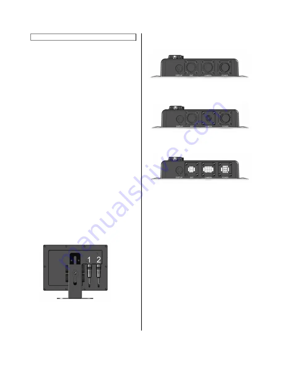
Display Connections
1 – Connect cable CVDC6MA (from
controller)
2 – Connect the Remote Control directly or
use the optional 5 meter extension cable
(CVDR5MA).
Controller Connections
CVS100XL
CVS100H
CVS100M
POWER – Using the provided cable connect
Red to post ignition vehicle power, Black to
chassis ground and Blue to reverse.
CAMERA – Car Vision camera input. This
position is activated via the blue reverse wire as
well as when the display is turned on manually
via the remote.
EXT – External Video output/input activated via
the EXT button on the remote. Pressing EXT
again will switch back to the camera input.
Note: EXT IN must be set to ON in the installers
menu to allow for external video input operation.
DISPLAY – Connects the controller to the
display via the CVDC6MA cable provided with
the controller.


