


© INTEC Video Systems, Inc.
Revision F May, 2013
12
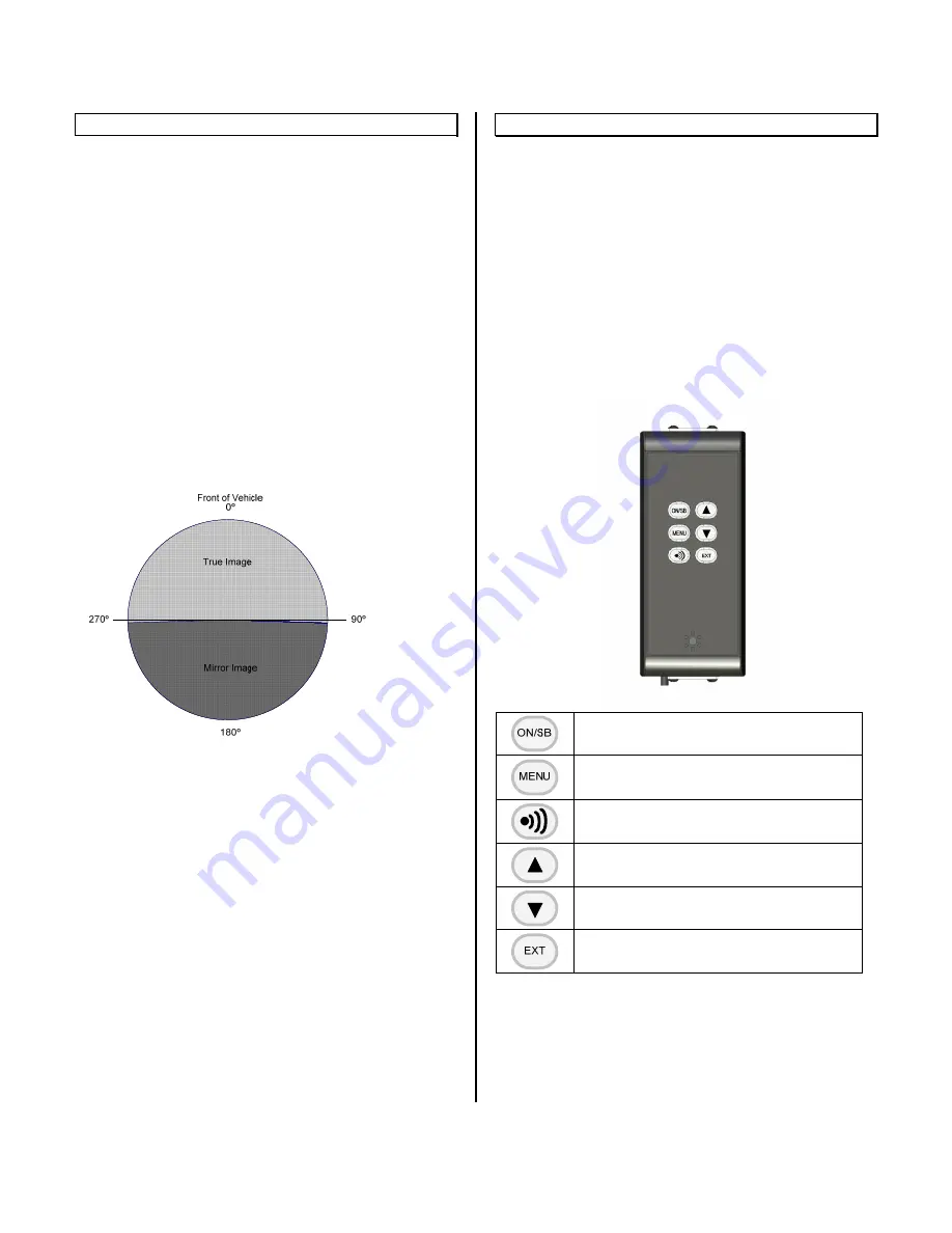
Image Orientation
The orientation of the image displayed is critical to
safe vehicle operation. An object on the right side of
your vehicle needs to be seen on the right side of
the displayed image.
Orientation Requirements
Generally, if your display is facing rearwards, you
would want a Mirror image displayed from a camera
facing rearward and a True image displayed from a
camera facing forward. The image orientation of
cameras on the right or left side of a vehicle
depends on how far off of center they are facing. For
example; a camera mounted on the right side at 90º
off of the front would usually require a true image to
be displayed. But set the camera to 91º off of the
front and a mirror image may be required. Be sure to
confirm the image(s) displayed are appropriate for
your application before operating the vehicle.
How to Change Your Image
INTEC’s CVC Series cameras are set as default at
the factory to display a mirror image when used with
our CVD or CVM Series displays and monitors.
Should you need to change the default image, you
have the option of changing it at the camera or the
display (see the Operating Instructions for
information on changing the image at the display).
Note:
Not all INTEC cameras can be changed in the
field; some may need to be returned to INTEC to
have the image changed. Refer to your camera’s
Operation Manual for information on your particular
camera. Always confirm proper orientation before
operating your vehicle.
Operating Instructions
Controller Operation
The CVS100 controller does not have any
independent controls. All adjustments are made via
the remote control and are dependent upon the
controller and software version used.
Refer to the displays ON-Screen Menu for
information regarding the software version installed
there.
CVR100 (Single Channel Remote)
- Manually turns the display on or places it in
standby.
- Accesses the on-screen menu.
- Continue pressing Menu to scroll through the
menu items.
- Adjusts the radar audible alert between three
available preset levels. (Active when used with a
compatible radar system)
- Increases screen brightness.
- Increases the value of a menu item
- Decreases screen brightness.
- Decreases the value of a menu item.
- Selects the external video input. (Must be set to
on before it can be selected).


