INTEC Controls | 12700 Stowe Drive, Suite 100, Poway, CA 92064 | Ph: (858) 578.7887 & (888) GO.INTEC | inteccontrols.com
Specifications subject to change without notice. | GAMSC2_E_0619 | USA 200309 | Page 8 of 17
DC6 – UserManual
INTEC Controls | 12700 Stowe Drive, Suite 100, Poway, CA 92064 | Ph: (858) 578.7887 & (888) GO.INTEC | inteccontrols.com
Specifications subject to change without notice. | USA 200304 | Page 4 of 5
DC6
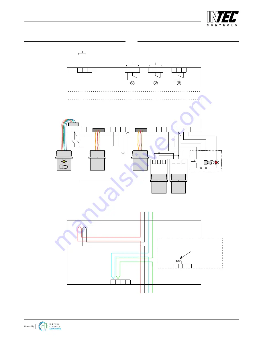
WIRING CONFIGURATION
DC6 Sensor Board
1 2 3
1 2 3 4
Digital (Binary)
Inputs
Digital Inputs
Analog
Output
Field Bus
Analog
Inputs
Digital
Output
F_Bus_A
F_Bus_B
4-20 mA
Local Bus_1
Local Bus_2
24 VDC
AI_01
AI_02
NC
GND
Horn
Strobe Light
F_Bus_A
F_Bus_B
AO_01
GND
DI_1
DI_2
GND
GND
1 2 3 4 5 6 7
X11
X12
X13
X1
3 2 1
X2
3 2 1
X3
3 2 1
X4
3 2 1
24 VDC
GND
4-20 mA
1 2 3
24 VDC
GND
1 2 3
4-20 mA
AT6
Sensor 1*
AT6
Sensor 2*
SC2
Sensor 1*
* Note: Combination of (3) total sensors allowed:
(
2) local SC2 s (1) remote AT6 sensor;
(
1) local SC2 (2) remote AT6 sensors;
SC2
Sensor 2*
24 VDC
0 VDC
NC
Relays drawn de-energized.
Relay Mode = Energized (Alarm ON = Relay OFF)
Signal
Relay 1
Signal
Relay 2
Signal
Relay 3 (Fault)
Power Supply
1 2
F_Bus_A
F_Bus_B
X12
X1
3 2
24 VDC
0 VDC
Field Bus
24 VDC 0 VDC F_Bus_A F_Bus_B
DC6
DC6
Last Device on Trunk Segment
If this DC6 is the last
device on a PG2 trunk
segment, use a 560
Ω
resistor at terminal X12
pins 1 and 2.
F_Bus_A
F_Bus_B
1 2 3 4
X12


