


AirGate-Modbus
INTAB INTERFACE-TEKNK AB
4/22
INSTALLATION RECOMMENDATIONS
Input conductors must go through the system plant separated from the output and power supply conductors, in grounded
conduits.
OPERATION
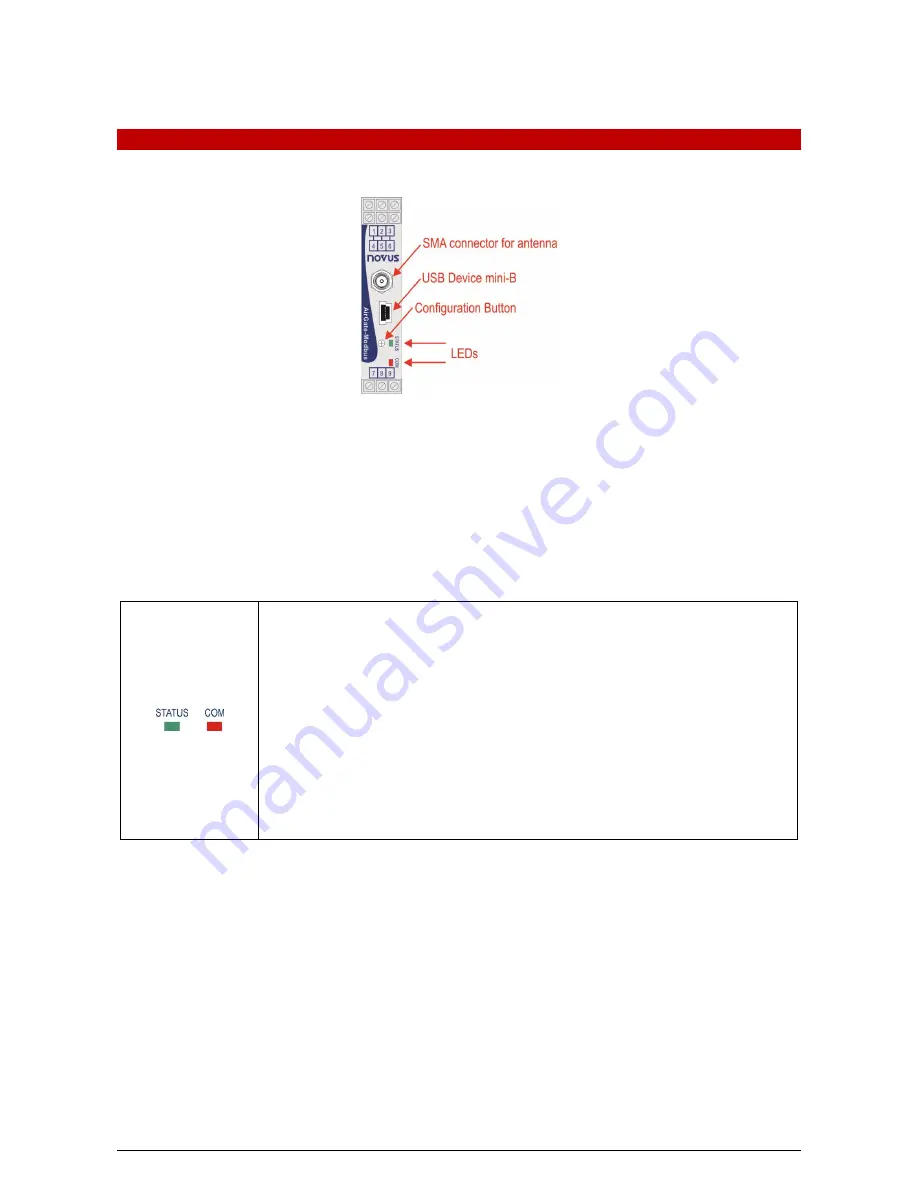
In the frontal panel are found an mini-B USB connector, a SMA connector for the antenna, a setup button and two LEDs for status
indication. See
Fig. 4
.
Fig. 3 -
AirGate-Modbus
frontal panel
USB
The USB interface of
AirGate-Modbus
is used for setup. Depending on the operation mode set, this interface can be connected to a
PC functioning as master of the Modbus RTU network.
SETUP BUTTON
When press the button,
AirGate-Modbus
enters setup mode and waits the configuration by the USB interface. If there is no
communication through the USB interface, after 1 minute, this will go back to normal functioning.
LEDS
When turning the equipment on, the Status LED starts to flash quickly until the
AirGate-Modbus
connects to a wireless network. In the moment that the
AirGate-Modbus
is connected to a wireless
network, the Status LED remains turned on.
When the setup button is pressed, the Status LED flashes slowly until
AirGate-Modbus
quits
operation mode. There are 3 possible ways to quit setup mode:
Clicking in the setup button again;
Applying a configuration successfully;
Waiting 1 minute.
The Communication LED flashes to show that the device is receiving packages through any of its
interfaces and is forwarding correctly. The speed of the flashing is according to the communication
speed.
When the Firmware of the
AirGate-Modbus
is being updated, the Communication LED will start to
flash and the LED Status will be off.


