background image

© Intatec Ltd 2016

1

Contents 

    Thank you for choosing the Inta lever operated thermostatic wall mixer.


Subject                                                      Page


Introduction                                                                              2

        Technical Data                                                                          2

        Components - Wall Mounted                                                      3

        Components - Wall Mounted with Removable Spout                      4

        Components - Deck Mounted                                                      5

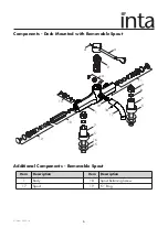
        Components - Deck Mounted with Removable Spout                      6

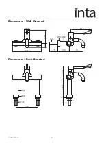
        Dimensions                                                                               7

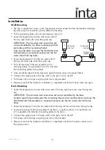
        Installation                                                                                8

        Operation                                                                                9

        Trouble Shooting                                                                       9

        Re-calibration                                                                           10

        Cartridge Removal                                                                   10

        Aftercare                                                                                 11

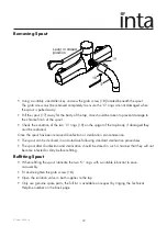
        Removing Spout and Disinfection                                               12

        System Flushing Procedure                                                        13

        Sterilization Process                                                                  14

        TMV3 Installation Instructions                                                     16

        Guarantee                                                                               21

Summary of Contents for HTMDMCP

Page 1: ...information as accurate as possible We cannot accept any responsibility should it be found that in any respect the information is inaccurate or incomplete or becomes so as a result of further develop...

Page 2: ...3 Components Wall Mounted with Removable Spout 4 Components Deck Mounted 5 Components Deck Mounted with Removable Spout 6 Dimensions 7 Installation 8 Operation 9 Trouble Shooting 9 Re calibration 10 C...

Page 3: ...t attempt to install your control mixer until the missing parts have been obtained Product Range HTMWMCP HTM safe touch thermostatic sequential wall mounted tap HTMDMCP HTM safe touch thermostatic seq...

Page 4: ...egulator 3 Lever 4 Lever Retaining Screw 12 Hot Water Inlet Assembly including 5 l m flow regulator 5 Concealing Plate 6 Cold Water Inlet Tail Assembly 13 Hot Water Port Blanking Assembly 7 Hot Water...

Page 5: ...Item Description Item Description 1 Body 18 Spout Retaining Screw 17 Spout 19 O Ring Components Wall Mounted with Removable Spout Additional Components Removable Spout 1 2 3 4 5 6 5 7 8 9 11 13 14 15...

Page 6: ...3 Lever 4 Lever Retaining Screw 12 Hot Water Inlet Assembly including 5 l m flow regulator 5 Concealing Plate 6 Cold Water Inlet Tail Assembly 13 Hot Water Port Blanking Assembly 7 Hot Water Inlet Ta...

Page 7: ...Item Description Item Description 1 Body 18 Spout Retaining Screw 17 Spout 19 O Ring Components Deck Mounted with Removable Spout 1 2 3 4 11 6 5 8 9 7 5 13 14 16 15 10 12 17 18 19 Additional Componen...

Page 8: ...Intatec Ltd 2016 7 Dimensions Wall Mounted Dimensions Deck Mounted 37 G B 128 75 105 186 5 45 266 116 5 50 33 75 187 5 200 G B 50 33 100...

Page 9: ...y pipes to the tap cold on the right hot on the left Fit the lever 3 to the tap using the grub screw 4 provided Please ensure that the hydraulic installation is completed and that all check valves are...

Page 10: ...tored hot water supply Ensure that the boiler is still firing for combi boilers Adjust the boiler control to a minimum setting of 65 C not necessarily the best flow rate Temperature is too hot or when...

Page 11: ...wn These two rings are used to prevent the temperature of the cartridge from being altered whilst in use The stop rings should be locked at either end of the operating cycle and will form a physical s...

Page 12: ...this fitting is serviced at least once a year Only use genuine spare parts the full list is available on request by ringing the Technical Helpline number on the back page Removing Spout The HTMWMRS wa...

Page 13: ...een removed disinfection or sterilisation can commence The spout can be sterilised in an Autoclave following standard sterilisation procedures The spout after disinfection and sterilisation should be...

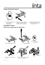
Page 14: ...uct and invalidate the product guarantee A Waste water flushed through outlet with hose connected 7 Flushing hose not supplied 90 OPEN CLOSE 1 Move handle to closed position Water must not pass throug...

Page 15: ...9 Unscrew the connector plug using suitably sized spanner and refit the check valve and end cover 10 Repeat the procedure for the cold inlet side before opening both isolation valves REMOVE 1 Move han...

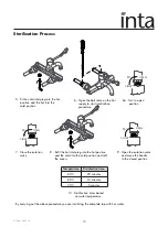
Page 16: ...hot supply to start sterilization procedure 90 OPEN CLOSE 6A Turn to open position 7 Close the isolation valve 90 OPEN CLOSE 8 Refit the hot inlet plug into the hot position and the cold into the col...

Page 17: ...been independently tested and approved as a TYPE 3 valve under the TMV3 scheme Technical Specification Application This thermostatic mixer has been independently tested by WRc and certified as meetin...

Page 18: ...which the Thermostatic Mixing Valve is to be installed into must be thoroughly flushed and cleaned to remove any debris see page 13 which may be accumulated during the installation Failure to remove a...

Page 19: ...nsure that the system is thoroughly cleaned and free from any debris prior to the commissioning of the valve See page 10 2 The commissioning of the temperature must be carried out using a suitably cal...

Page 20: ...ated on every occasion when any work is carried out on the valve In Service Testing To ensure that the Thermostatic Mixer maintains a high level of protection we advise the following in service testin...

Page 21: ...ng and 5 of this section the next in service testing should be carried out at a period of 24 to 28 weeks after initial commissioning b If a small change e g 1 2 C in the mixed water temperature is rec...

Page 22: ...and supplier s name is presented with the defective product within the guarantee period The free of charge service may be refused if this information is not available The guarantee will not apply if...

Page 23: ...Intatec Ltd 2016 22 Notes...

Page 24: ...n Staffordshire ST18 0PF Tel 01889 272 180 Fax 01889 272 181 email sales intatec co uk web www intatec co uk E O E 10 08 16 To activate your product warranty please visit www intatec co uk and click o...

Reviews: