INSTEON 2486DWH6 User Manual Download Page 11

INSTEON KeypadLinc Dimmer User’s Guide 


Page 11 of 39 


Step-by-Step Instructions for Installing Multi-Way KeypadLinc Dimmers 

When replacing a three-way mechanical switch, each switch will have three wires connected to it from the 
wall box.  Four-way or greater circuits will have four wires connected to the switches in the center of the 
circuit.  For this tutorial, we will follow the most commonly used wire colors for homes in North America. 

1. 

Find the LINE wire.

  Your first task is to find out which switch 

junction box is the one where the electricity comes into the circuit.  
This box will contain the LINE wire (sometimes called HOT). 

a.  Turn off the electricity at the circuit breaker panel.  

b.  Pull all the switches in the multi-way circuit out of their junction 

boxes.  Each switch should have three wires connected to it.  If 
the circuit is a four-way or greater, some of the switches will 
have four wires. 

c.  Disconnect the wires from the old switches.  If the wires cannot be detached by unscrewing them, 

cut the wires where they enter the switch, then strip ½ inch of insulation off the ends. 

d.  Making sure that none of the wires are touching anything and that no one is around the wall 

boxes, turn the electricity back on. 

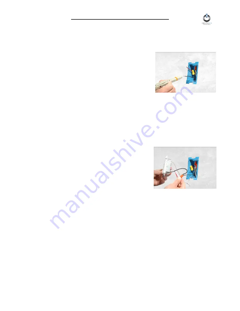
e.  Using a voltmeter or voltage sensor, individually test each wire for voltage.  When you measure 

120 Volts AC, that wire is the LINE wire.  LINE wires are usually black. 

f.  The other two wires usually black and red, are the TRAVELERS and go to the next junction box.  

TRAVELER wires are usually in the same cable sheath. 

g.  Turn off the electricity to resume installing the new KeypadLinc Dimmers.  

2. 

Connect the KeypadLinc Secondary’s LINE Wire.

  The 

KeypadLinc Dimmer that will be the Secondary goes in the 
junction box where you found the LINE wire.  Connect the black 
LINE wire that you found, the black TRAVELER, and the Black 
LINE wire on KeypadLinc Dimmer all together with a single wire 
nut.  If another type of  INSTEON or X10 device is to be installed 
as the secondary switch, installation is likely as described above, 
but you should verify the installation instructions specific to that 
device. 


Summary of Contents for 2486DWH6

Page 1: ...INSTEON KeypadLincTM Dimmer Rev 1 5 INSTEON Keypad Dimmer For models 2486DWH6 KeypadLinc Dimmer 6 Button 2486DWH8 KeypadLinc Dimmer 8 Button...

Page 2: ...m an INSTEON Controller 19 HOW TO SET UP ON LEVELS AND RAMP RATES 20 Setting the On Level 20 Setting the On Level and Ramp Rates Optional 20 Setting the Ramp Rate 21 Locking In a Remote Controlled On...

Page 3: ...Use custom etched button to make your KeypadLinc your own 32 ABOUT INSTEON 33 Understanding Why an INSTEON Network Is Reliable 33 Further Enhancing Reliability 33 Using SmartLabs Access Point Modules...

Page 4: ...uses existing power line wiring as well as radio frequency RF for communication Reliable because every INSTEON device is a two way repeater And affordable not just because of low cost but because INST...

Page 5: ...re to KeypadLinc Dimmer Before installing disconnect power at the circuit breaker or remove the circuit s fuse to avoid shock or possible damage to KeypadLinc Dimmer It is recommended that a qualified...

Page 6: ...o If your junction box does not contain a neutral wire please call Smarthome Tech Support at 800 SMARTHOME 800 762 7846 or consult an electrician Don t use KeypadLinc Dimmer to control low voltage lig...

Page 7: ...ion of the switch and seven programmable secondary buttons Attach the change out plate to the switch body by aligning the tabs and snap into place Button Nomenclature Since KeypadLinc Dimmer has remov...

Page 8: ...ires correctly before connecting them 6 If you are installing KeypadLinc Dimmer into a multi way circuit where more than one switch controls the same load follow the instructions in the section titled...

Page 9: ...nly found are circuits that are 4 way or above You can use KeypadLinc Dimmers to replace switches in existing multi way circuits or you can use them to create virtual multi way circuits without the ne...

Page 10: ...he other TRAVELER number 2 the black one you will convert to a LINE wire In the junction box where the KeypadLinc Secondary is connect TRAVELER 2 to the existing LINE and also to the KeypadLinc Second...

Page 11: ...the wires cannot be detached by unscrewing them cut the wires where they enter the switch then strip inch of insulation off the ends d Making sure that none of the wires are touching anything and that...

Page 12: ...the KeypadLinc Secondary s LOAD wire to ensure that it won t connect to anything 5 Connect the KeypadLinc Secondary s NEUTRAL Wire Locate the group of NEUTRAL wires usually white in the rear of the bo...

Page 13: ...alled the LOAD wire is commonly red In the same junction box there will also be the two TRAVELER wires from the first box often both in the same cable sheath Identify the one TRAVELER wire black that...

Page 14: ...ights those extra switches will have four wires connected to them Two of the wires are TRAVELERS from the preceding switch and the other two are TRAVELERS to the next switch in the chain You will be c...

Page 15: ...ing in eight button mode If KeypadLinc Dimmer is to be changed from eight button to six button configuration replace the eight button plate with the six button plate Gently pull the SET Button at the...

Page 16: ...er Press and hold the SwitchLinc Dimmer s Paddle Top for 10 seconds then release To confirm linking the SwitchLinc Dimmer will blink the top LED in its LED Bar and flash the light that it is wired to...

Page 17: ...up You can link multiple INSTEON Devices to multiple INSTEON Controllers To add an additional INSTEON Device to a scene controlled by KeypadLinc Dimmer simply follow the same procedure as above in Lin...

Page 18: ...roller Choose the ON OFF Button Pair you want to use for controlling KeypadLinc Dimmer Press and hold the ON Button of the pair for 10 seconds To confirm that it is in Linking Mode ControLinc s Status...

Page 19: ...Controller Press and hold the OFF Button of the ON OFF Button Pair you used for controlling KeypadLinc Dimmer for 10 seconds To confirm that it is in Unlinking Mode ControLinc s Status LED will begin...

Page 20: ...On Level and Ramp Rate values apply when you tap the On Button or Off Button on KeypadLinc Dimmer itself Remote Controlled On Level and Ramp Rate values apply when another INSTEON Controller tells Ke...

Page 21: ...the same as linking Just follow the instructions in the section Linking an INSTEON Controller to KeypadLinc Dimmer above Linking an INSTEON Controller to KeypadLinc Dimmer restores the previous values...

Page 22: ...N OFF status and brightness level on the LED bar of the other switches it has been cross linked to Cross Linking in a Multi Way Circuit using Multi Link Mode For more than two switches or KeypadLinc m...

Page 23: ...ON indicating that the factory reset is complete KeypadLinc Dimmer is now reset to all the default settings and ready for fresh programming and use Keypads purchased as six button will reset to six bu...

Page 24: ...roblems For clarity s sake the following instructions will refer to the two buttons to be added to a group as button A and button B The below instructions refer to cross linking buttons A B twice Firs...

Page 25: ...s the C and F buttons and then release o Adjust the Local load brightness level Hold down KeypadLinc Dimmer s On Off Button s to brighten or dim the controlled light o Simultaneously press the C and F...

Page 26: ...KeypadLinc Dimmer has received the X10 Address three times KeypadLinc Dimmer will confirm that it has set its Primary X10 Address by blinking its LED and flashing the light that it is wired to Removi...

Page 27: ...r the last brightness level to which it was set Then when an ON command is received from a controller or the load is turned on from the KeypadLinc the light will go to the remembered brightness rather...

Page 28: ...y adjusting KeypadLinc Dimmer s brightness using its on off buttons or any Controller If you skip this step the current On Level will be used 4 Send the following X10 Address sequence to lock in the n...

Page 29: ...ene Address and On Level 1 Using an X10 Controller send the CLEAR Sequence 2 Set the On Level for the X10 Scene Address by adjusting KeypadLinc Dimmer s brightness using its on off buttons or any Cont...

Page 30: ...code 3 Use any controller to adjust KeypadLinc Dimmer s brightness so it corresponds to the Ramp Rate you want in the table below If you use KeypadLinc Dimmer s on off buttons and you are careful you...

Page 31: ...ess and hold the Off Button to gradually dim your light from whatever brightness it currently has to full OFF Button Tap Double Tap Press and Hold On Ramp to On Level Fast ON Brighten Off Ramp to OFF...

Page 32: ...entle in removing the keys The buttons on the KeypadLinc require extra special care in removing the keycaps Using a small flat edged screwdriver ONLY pry up on the sides of the keys from the middle of...

Page 33: ...r line You can temporarily unplug suspected devices to test whether the INSTEON signal improves If it does then you can plug in AC line filters available from Smarthome to permanently fix the problem...

Page 34: ...chnology that you can turn on or turn off when you set the X10 Address for the product If turned on the BoosterLinc technology may interfere with INSTEON KeypadLinc 6 with Integrated Dimmer 12073W 120...

Page 35: ...not linking to or working with an INSTEON Controller or Device The INSTEON signal may be too weak Make sure you are not experiencing interference with older X10 BoosterLinc technology Upgrade to INSTE...

Page 36: ...ress by following the instructions in the section Setting the X10 Primary Address I m having difficulty performing advanced X10 programming The X10 MNOP house and unit codes were sent in the wrong ord...

Page 37: ...EON X10 INSTEON cleanup Multi Way Circuit Support One KeypadLinc Dimmer controls load Cross Link any number of KeypadLinc Dimmers or other INSTEON Controllers Setup Memory Non volatile EEPROM INSTEON...

Page 38: ...o the immediate right or left Use a triple gang box with a mechanical switch in the center to avoid de rating Operating Conditions Indoors 40 to 104 F up to 85 relative humidity Dimensions 4 1 H x 1 8...

Page 39: ...age the product with the RA clearly printed on the outside of the package and send the product along with all other required materials to SmartLabs Inc ATTN Receiving Dept 16542 Millikan Ave Irvine CA...

Reviews: