background image

INSTEON-compatible AccessPoint User’s Guide 


Install the AccessPoint 

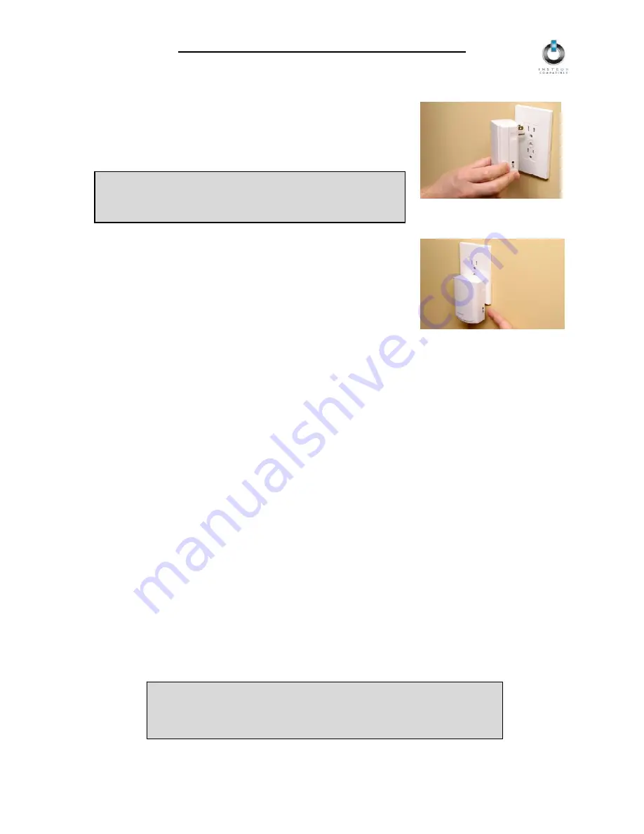
1.  Plug the First AccessPoint into a convenient wall outlet.  Don’t use 

an outlet controlled by a switch, because if the switch is 
inadvertently turned off, AccessPoint won’t have power.  The white 
Status LED on the side will illuminate steadily, indicating that 
AccessPoint is working. 


TIP 

Choose an outlet that is not near large metal objects which 
might absorb radio-frequency signals. 

2.  Put the First AccessPoint into Setup Mode by rapidly pressing the 

SET Button

 on the side four times.  The Status LED will turn and 

remain bright once AccessPoint has entered Setup Mode. 


Install the Second AccessPoint (or any subsequent AccessPoints) 

1.  You have about 9 minutes to perform these steps before Setup Mode on the First AccessPoint will 

time out automatically.  If the First AccessPoint does time out, simply put it back into Setup Mode and 
you will have another 9 minutes. 

2.  Locate another unswitched outlet, preferably on the other side of your home, and plug the Second 

AccessPoint into it. 


3.  Observe the Status LED on the Second AccessPoint. 

Bright and 

Steady 


Blink or Dim 


A. If the 

Status LED is bright and steady

 the two AccessPoints are 

communicating with each other and plugged into outlets on 

opposite 

powerline phases

.  

This is what you want

 – both powerline 

phases can now communicate with each other via the two 
AccessPoints.  Proceed to step 4. 

B. If 

the 

Status LED blinks or remains steady at a dim level

 the two 

AccessPoints are either unable to communicate, or can 
communicate but are on the same powerline phase.  In either case, 
unplug the second AccessPoint and try locating it to another outlet.  
Repeat as necessary until you observe the 

bright steady Status 

LED

 described above.  Proceed to step 4 once this is achieved. 


NOTE 

If you can’t locate a pair of outlets on opposite powerline phases, contact 
your local installer or SmartLabs Tech Support at 866-243-8018 for 
further assistance. 

Page 5 of 12 


Summary of Contents for 2443

Page 1: ...INSTEON AccessPoint INSTEON RF Receiver RF PLC Bridge For models 2443 AccessPoint 2443P AccessPoint two pack ...

Page 2: ...stall the AccessPoint 5 Install the Second AccessPoint or any subsequent AccessPoints 5 Installing Additional AccessPoints 6 ABOUT INSTEON 7 Understanding Why an INSTEON Network Is Reliable 7 Further Enhancing Reliability 7 Using SmartLabs AccessPoint to Upgrade Your INSTEON Network 7 About INSTEON and X10 8 TROUBLESHOOTING 9 SPECIFICATIONS 10 AccessPoint Specifications 10 FCC Compliance Statement...

Page 3: ... is a breeze and there are no wires to add INSTEON uses existing powerline wiring as well as radio frequency for communication Reliable because every INSTEON device is a two way repeater And affordable not just because of low cost but because INSTEON also works with legacy X10 devices An INSTEON home grows in value with every INSTEON device you add making life more convenient safe and fun Key Acce...

Page 4: ... plug AccessPoint into an outlet controlled by a switch because if the switch is inadvertently turned off AccessPoint will not have power Do not plug AccessPoint into a filtered power Locate AccessPoints in different areas of the home keeping the each other In multi level Do not place AccessPoint near large metal objects like AccessPoint works best when placed out in the open Unlike many INSTEON d...

Page 5: ...nto Setup Mode and you will have another 9 minutes 2 Locate another unswitched outlet preferably on the other side of your home and plug the Second AccessPoint into it 3 Observe the Status LED on the Second AccessPoint Bright and Steady Blink or Dim A If the Status LED is bright and steady the two AccessPoints are communicating with each other and plugged into outlets on opposite powerline phases ...

Page 6: ...g Additional AccessPoints You can add additional AccessPoints to your INSTEON network to extend its coverage and maximize performance Simply choose the AccessPoint that you previously installed as the First AccessPoint and follow the steps above to confirm that new AccessPoints are communicating with your existing AccessPoints After the two opposite powerline phases in your home are coupled with a...

Page 7: ... way to overcome signals getting weaker is to increase the coverage of the mesh network by introducing more INSTEON devices It is possible that TVs PCs power strips or other electrical equipment may attenuate INSTEON signals on the powerline You can temporarily unplug suspected devices to test whether the INSTEON signal improves If it does then you can plug in filters such as SmartLabs FilterLinc ...

Page 8: ...or turn off when you set the X10 Address for the product If turned on the BoosterLinc technology may INSTEON interfere with 1 Press and hold the SET Button 2 Send the X10 Primary Address 3 Send an X10 OFF Command You can send an X10 ON Command in Step 3 to re enable the BoosterLinc feature To disable BoosterLinc X10 Signal Boosting on these products NOTE KeypadLinc 6 with Integrated Dimmer 12073W ...

Page 9: ...tried several outlets and the Second AccessPoint s Status LED is blinking or steadily on at dim level Something made of metal is blocking the wireless signal Move AccessPoints away from metal objects The Status LED has turned off and does not flicker during INSTEON transmissions A surge or excessive noise on the powerline may have locked up AccessPoint Unplug AccessPoint for 10 seconds and reinsta...

Page 10: ...er SBP2443 INSTEON Powerline Features INSTEON Powerline Frequency 131 65 KHz INSTEON Minimum Transmit Level 3 2 Vpp into 5 Ohms INSTEON Minimum Receive Level 1 mVpp nominal INSTEON Messages Repeated Yes X10 Features X10 Messages Repeated No Mechanical Operating Conditions Indoors 0 to 70 C up to 85 relative humidity Dimensions 4 0 H x 2 5 W x 1 25 D Weight 3 6 oz Electrical Supply Voltage 120 Volt...

Page 11: ...uency energy and if not installed and used in accordance with the instructions may cause harmful interference to radio and television reception However there is no guarantee that interference will not occur in a particular installation If this device does cause such interference which can be verified by turning the device off and on the user is encouraged to eliminate the interference by one or mo...

Page 12: ...uct with the RA clearly printed on the outside of the package and send the product along with all other required materials to SmartLabs Inc ATTN Receiving Dept 16542 Millikan Ave Irvine CA 92606 5027 Limitations The above warranty is in lieu of and seller disclaims all other warranties whether oral or written express or implied including and warranty or merchantability or fitness for a particular ...

Reviews: