Inscape Data AirGoggle NVC360 Quick Install Manual Download Page 6

Q

Q

U

U

I

I

C

C

K

K


R

R

E

E

F

F

E

E

R

R

E

E

N

N

C

C

E

E


G

G

U

U

I

I

D

D

E

E


6


2

2

.

.


I

I

n

n

s

s

t

t

a

a

l

l

l

l

a

a

t

t

i

i

o

o

n

n


a

a

n

n

d

d


I

I

P

P


a

a

l

l

l

l

o

o

c

c

a

a

t

t

i

i

o

o

n

n


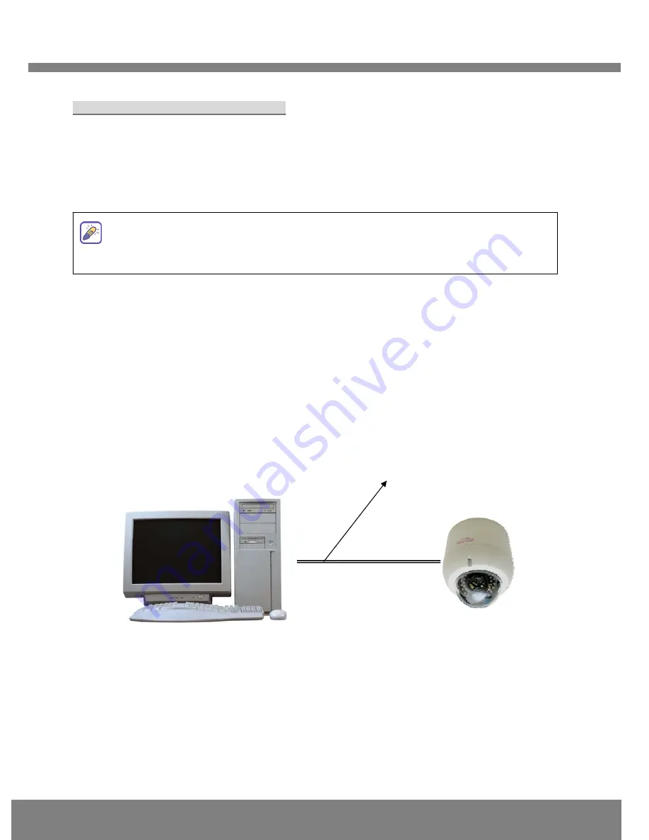
The setup in this guide utilizes a crossover cable connection between the NVC units and 
installation computer as shown in figure 2-1 for easy installation and demonstration of basic 
feature sets. The NVC supports network configurations including LAN, ADSL modem, and cable 
modems including IP sharing devices.  Use normal Ethernet cables in most cases unless 
connecting directly between the installation PC and the NVC. 


2

2

.

.

1

1

.

.


Q

Q

u

u

i

i

c

c

k

k


I

I

n

n

s

s

t

t

a

a

l

l

l

l

a

a

t

t

i

i

o

o

n

n


O

O

r

r

d

d

e

e

r

r


In order to check the functionality of the product, please follow the 3 steps below: 


Connect the installation computer and the NVC product via a crossover Ethernet cable. 


Install the IP-Installer program on the installation computer. 


Assign an IP address to the NVC product with the IP-Installer. 


2

2

.

.

2

2

.

.


C

C

o

o

n

n

n

n

e

e

c

c

t

t

i

i

n

n

g

g


P

P

C

C


a

a

n

n

d

d


t

t

h

h

e

e


P

P

r

r

o

o

d

d

u

u

c

c

t

t


  Figure 2-1 Connecting NVC and PC by cross type LAN Cable 

 Apply power to the installation PC and start Windows Operating System. 

For further information on LAN, xDSL, and cable modem connections, please refer to 
the user manual in the CD provided with the product. 


Client PC 

Crossover LAN Cable 

Summary of Contents for AirGoggle NVC360

Page 1: ...gle IP Video Camera QUICK INSTALL GUIDE Rev 0 2 April 2009 Corporate Headquarters Inscape Data Corporation 1611 South Main Street Milpitas CA 95035 USA http www inscapedata com Tel 408 935 8500 1 888...

Page 2: ...pter Input 100 250V 50 60Hz Output 12VDC 3 33A Standard Power AC power cable AC 250V 10A 16A Video cable Cable for analog video output from camera module inside of network camera CD ROM Software User...

Page 3: ...1 1 E Ex xt te er rn na al l a an nd d I In nn ne er r V Vi ie ew ws s Figure 2 1 External and inner views of NVC360 1 Surface mount adaptor 2 Cap screw PT3 4 1EA 3 Main body 4 Focus handle 5 Zoom han...

Page 4: ...RE EF FE ER RE EN NC CE E G GU UI ID DE E 4 1 3 2 Dip Switch Setting A DIP SWITCH SETTING FLK Flickerless ON OFF BLK BLC ON OFF LED H IR LED Illumination High power VIDEO DC LEVEL SENSITIVITY DIP SWI...

Page 5: ...When you use pipe please note the standard size of pipe FIG 6 2 Fix the main body on the surface mount adapter by screws FIG 7 3 Push and open gimbals and adjust desired focus and scene by turning and...

Page 6: ...d the NVC 2 2 1 1 Q Qu ui ic ck k I In ns st ta al ll la at ti io on n O Or rd de er r In order to check the functionality of the product please follow the 3 steps below Connect the installation compu...

Page 7: ...m m Fig 2 2 Initial mode of IP Installer Network Adapter Selection on Window 2000 or XP If using Windows 2000 or XP the PC will ask you to select the proper network adaptor as in Figure 2 3 It is impo...

Page 8: ...he combinations of network type and IP allocation methods Network Mode can be LAN Automatic ADSL Static ADSL Automatic Cable Modem Static Cable Modem Automatic which you can choose from Settings can v...

Page 9: ...e are two ways to check the video transmission from the unit Using NVR100 the stand alone software for multi channel viewing and recording Using the conventional web browser Internet Explorer 3 3 1 1...

Page 10: ...t dw2001 and click at the bottom of the window then the values set will be saved Please make sure that Store Pwd is checked before clicking Otherwise the values will not be saved Fig 3 2 NVR100 IP Add...

Page 11: ...via your favorite web browser in addition to the NVR100 software In order to access the unit you must type in the appropriate IP address in the browser Fig 3 4 is an example of the web interface Fig...

Reviews: