INSTALLATION, SERVICE AND MAINTENANCE INSTRUCTIONS
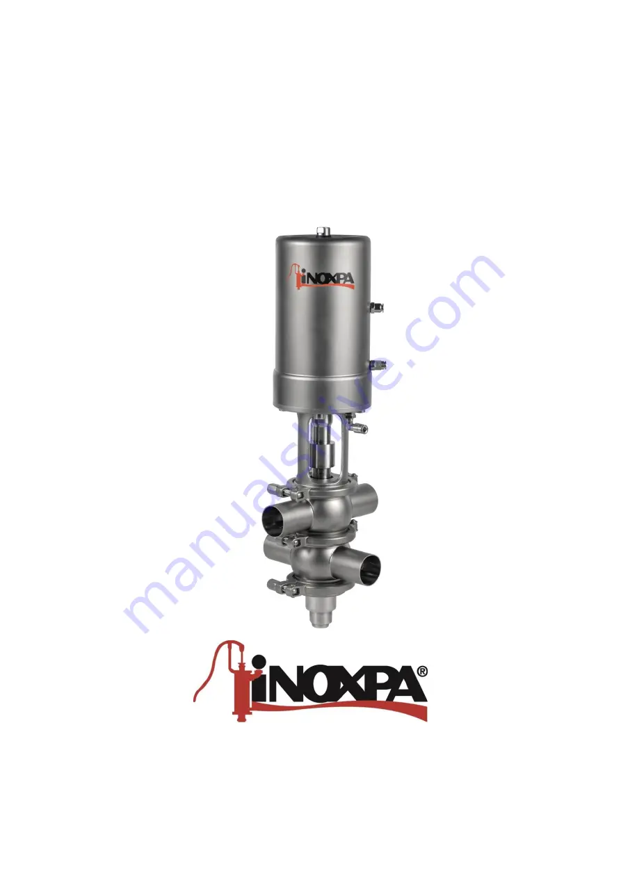
DOUBLE SEAT VALVE
INNOVA P
Original manual
10.250.30.02EN
(0) 2019/09
1
0
.2
5
.3
2
.0
Page 1: ...INSTALLATION SERVICE AND MAINTENANCE INSTRUCTIONS DOUBLE SEAT VALVE INNOVA P Original manual 10 250 30 02EN 0 2019 09 10 250 32 0025 ...
Page 2: ...odel INNOVA Type INNOVA P From serial number IXXXXXX to IXXXXXX 1 XXXXXXXXXIIN to XXXXXXXXXIIN 1 Fulfills all the relevant provisions of the following directive Machinery Directive 2006 42 EC Pressure Equipment Directive 2014 68 EU In compliance with Regulation EC nº 1935 2004 on materials and articles intended to come into contact with food The technical file has been prepared by the signer of th...
Page 3: ...General installation 9 5 6 Checking and review 9 5 7 Welding 10 5 8 Valve configuration with actuator 10 5 9 Actuator air connection 11 6 Start up 7 Operating problems 8 Maintenance 8 1 General considerations 14 8 2 Maintenance 14 8 3 Cleaning 15 8 4 Assembly and disassembly of the INNOVA P single seat valve 16 8 5 Replacing the seat seal 18 8 6 Disassembly and assembly of the actuator 19 9 Techni...
Page 4: ...s released 2 3 WARRANTY Any warranty will be void immediately and lawfully and additionally INOXPA will be compensated for any civil liability claims submitted by third parties in the following cases the service and maintenance work have not been carried out in accordance with the service instructions the repairs have not been carried out by our personnel or have been carried out without our writt...
Page 5: ...on The Technical specifications of chapter 9 should always be observed The specified limit values shall never be exceeded under any circumstance NEVER touch the valve and or piping that is in contact with the fluid during operation If the process involves hot products there is a risk of burns The valve contains parts that move in a linear fashion Do not place hands or fingers in the valve closing ...
Page 6: ...the plug shafts and the valve bodies 4 2 APPLICATION The INNOVA P valve is a double seat pneumatic shut off valve for hygienic applications which at atmospheric pressure between the two seats is formed a leak detection chamber which allows safe separation of two products one of which is usually CIP cleaning product The leak detection chamber is cleaned by the independent actuation of the seats dur...
Page 7: ... merchandise arrives to the user intact When receipt the valve remove any possible traces of packaging from the valve or its parts inspect the valve or the parts that comprise it for possible damage incurred during shipping take all possible precautions against damage to the valve and its components 5 2 TRANSPORT AND STORAGE The buyer or user shall be liable for assembly installation start up and ...
Page 8: ...2 S E NC 13 T3 S E NC Size 040 DN 40 OD 1 1 2 050 DN 50 OD 2 063 OD 2 1 2 065 DN 65 076 OD 3 080 DN 80 100 DN 100 OD 4 Seals 43 HNBR 52 EPDM 78 FPM Material 06 AISI 316L Connection 0 Welded Standard pipe 0 DIN 1 OD Body configuration A B C D 2 bodies J P R S V W X Z 3 bodies Types P Mixproof valve seat lift Product family WA INNOVA valve ...
Page 9: ...ore starting to weld the valve bodies to the pipe disassemble the valve to prevent damage to the joints following the instructions in section 8 4 Assembly and disassembly of the valve Avoid using excessive force when assembling the valves and pay special attention to vibrations that may be produced on the facility thermal dilation that the pipe may undergo when hot fluids are circulating the weigh...
Page 10: ...tc It is important to differentiate when the valve has a control head height B 5 8 VALVE CONFIGURATION WITH ACTUATOR The standard configuration of the valves is NC normally closed It is possible to convert them into NO Normally Open simply by turning the valve actuator see section 8 8 3 Actuator configuration Valves can also be configured as DE valves double effect Never disassemble the valve clam...
Page 11: ...valves are supplied with connections for Ø6 pipe and with a silencer on S E actuators Consider the quality of the compressed air according to the specifications described in chapter 9 Technical specifications Depending on the configuration the actuator may have one or two air connections G 1 8 threads pneumatic connections 10 250 32 0012 ...
Page 12: ...er check for possible leaks and make sure the pipes and their connections are sealed and do not have any leaks if the valve has been supplied with an actuator make sure that the alignment of the valve shaft and the actuator shaft enables smooth movement check that the compressed air pressure at the inlet to the actuator matches what is indicated in the 9 Technical specifications consider the quali...
Page 13: ...seal material and the product Normal seal wear Replace the seals Premature wear of the seal affected by the product Replace the seals with ones made of a different material or grade that is more appropriate for the product Reduce the pressure in the line Lower the operating temperature Product residue has deposited on the valve seat and or plug Clean frequently Product pressure exceeds the actuato...
Page 14: ...record of each valve noting any problems always having spare replacement seals in stock During maintenance pay special attention to the hazard warnings indicated in this manual The valve and the pipes must never be under pressure during maintenance During maintenance the valve must never be hot Burn hazard 8 2 1 Seal maintenance CHANGING SEALS Preventive maintenance Replace every 12 months Mainten...
Page 15: ...y will not be required EPDM is the standard seal material that will be used for CIP cleaning both in alkaline mediums and in acid mediums The other two options HNBR FPM are not recommended Cleaning solutions for CIP processes Only use clear water chlorine free to mix with the cleaning agents a Alkaline solution 1 by weight of caustic soda NaOH at 70ºC 150ºF 1 Kg NaOH 100 l H2O cleaning solution or...
Page 16: ...ator 10 so that the shafts 08 and 08A move to the open position 2 Loosen and remove the top clamp 34 between the top body 01 and the lantern 21 3 Remove the actuator 10 together with the valve shafts 08 and 08A from the valve bodies 01 and 01A 4 Release the compressed air from A2 on the actuator 10 5 Place the valve actuator assembly in a vertical position with the actuator at the bottom and the s...
Page 17: ...tor 10 11 Screw the bottom shaft 08A inside the top shaft 08 holding the top shaft to stop it from turning 12 Release the compressed air from A3 on the actuator 10 13 Fit the two O rings 20B on the intermediate cover 12A 14 Place the intermediate cover 12A over one of the valve bodies 01 and then place the other body on top 15 Install the intermediate clamp 34 joining these two bodies together 16 ...
Page 18: ...ate tool not piercing press the edge of the seal that hasn t yet fit into the accommodation as shown in the figure 6 This operation should be done around the entire diameter applying the tool in the sequence 1 2 3 4 5 6 7 8 as shown in the bottom figure Always press on opposite sides Once you get to the last step of this sequence repeat the process until the seal is completely inside the accommoda...
Page 19: ...20F the scraper 60C and the bushing 11D from the cover 12 7 Remove the seals 20C 20F from the piston 30A 8 Extract the bushing 11C and the seal 20E from the shaft sleeve 35 9 Extract the spring base 43B and spring 06A 10 Extract the spring assembly 06 without disassembling it Do not take the spring assembly 06 apart as it contains a spring with an applied charge Valve and or actuator assembly and ...
Page 20: ... the valve is used at high altitude or under low ambient temperature conditions the dew point must be adjusted accordingly Oil content quality class 5 preferentially oil free max 25 mg oil per 1m3 air Compressed air fitting G 1 8 Compressed air consumption litres N cycle DN Main movement Superior CIP Lower CIP 40 0 5 0 1 0 8 50 0 5 0 1 0 8 65 1 5 0 2 1 5 80 1 5 0 2 1 5 100 2 5 0 4 3 7 9 3 MATERIAL...
Page 21: ... 6 DIMENSIONS OF THE INNOVA P VALVE DN Weight kg DIN 40 5 3 50 9 1 65 16 80 17 100 33 OD 1 5 3 2 9 1 2 16 3 17 4 34 DN Dimensions mm A B ØF DIN 40 85 552 125 50 90 596 125 65 110 738 161 80 125 747 161 100 150 882 193 OD 1 85 552 125 2 90 603 125 2 110 737 161 3 125 747 161 4 150 882 193 10 250 32 0024 ...
Page 22: ...08 Top shaft 1 AISI 316L 08A Bottom shaft 1 AISI 316L 10 Actuator 1 AISI 304 11 11A Shaft bushing 2 PTFE 12 Body cap top bushing 1 AISI 316L 12A Upper bushing 1 AISI 316L 12B Bottom seal bushing 1 AISI 316L 12C Body cap bottom bushing 1 AISI 316L 17 Guide bushing 1 PTFE 20A 20B O ring 5 EPDM FPM HNBR 21 Lantern 1 AISI 304 23 Hexagonal screw 4 A2 23A Threaded bolt 1 A2 34 Clamp 3 AISI 304 35 Shaft ...
Page 23: ..._______________________________________________________________ ________________________________________________________________________________ ________________________________________________________________________________ ________________________________________________________________________________ ________________________________________________________________________________ ____________...
Page 24: ...anyoles Spain Tel 34 972 575 200 Fax 34 972 575 502 How to contact INOXPA S A U Contact details for all countries are Continually updated on our website Please visit www inoxpa com to access the information 10 250 30 02EN 0 2019 09 ...