


— 15 —
the display to flash with the alarm notification against a red
background to further make the alarm visible.
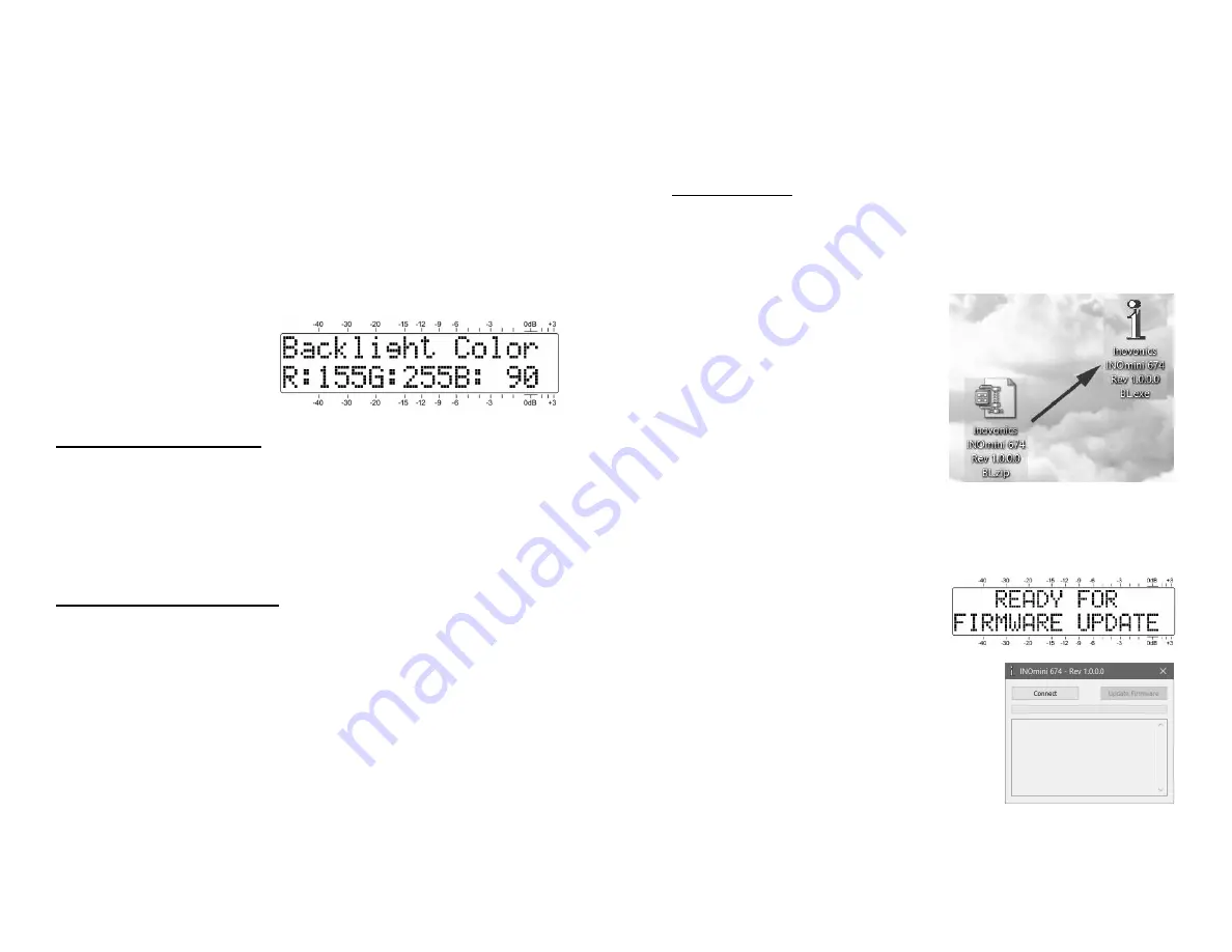
The backlighting has a range of R/G/B color rendering,
which can be applied universally to the menu trees, except
for the alarm condition. This menu screen allows you to set
the background to nearly any color you might wish to have.
Simply push the knob to sequentially access the
R:
(red),
G:
(green) and
B:
(blue) backlights, and set them selectively to
any of the 51 brightness levels offered, from
0
to
255
in in-
crements of 5.
We have established factory values for a nominally-white
background, although there may be variation in these set-
tings from unit-to-unit as the LCDs vary a bit. The color set-
tings shown here are
typical factory settings,
if you lose your way and
wish to get back close to
the original values.
Loading Factory Defaults
(Hidden Menu Screen 5)
With the exception of the backlight color settings, all main
and hidden menu selections can be put back to as-shipped,
factory values by invoking the
Load Defaults?
command.
With that menu selected, push the knob and turn it from
No
to
Yes
. When you then push the knob, the INOmini 674 will
reboot with factory defaults.
Returning to the Menu Tree
To get from hidden menu settings back to the normal, op-
erating menu tree, navigate back to Hidden Menu 1 (show-
ing
674 Firmware
) and push the knob.
— 16 —
Section IV
UPDATING FIRMWARE
Firmware Files
INOmini 674 firmware updates are issued at no charge
whenever operating features are changed or added. These
are small ‘bootloader’ files in a ‘zipped’ format that will be
available as downloads on the Inovonics Website.
The first step is to connect
your INOmini 674 to your com-
computer with a popular ‘USB-
A’ to ‘mini-B’ USB cable.
Next, download the zipped file
to your Windows Desktop and
unzip it in place, as was done
here. Simply double-click the
zipped
BL.zip
file and follow
the unzip utility’s instructions,
placing the extracted .exe file on the desktop.
Next, place the INOmini 674 in its ready-state to accept
firmware updates. Just unplug the 12VDC power connector
from the rear panel, and then hold-down the front-panel
knob as you plug the power
connector back in. This should
bring-up the wording shown at
the right.
Double-click the extracted
BL.exe
file,
which will include the product model
number and firmware version in its
full name. This will start the boot-
loader utility window shown here.
Click
Connect
and the utility should
quickly advise you that it has found
your INOmini 674. You can then
click
Update Firmware
and the update process will begin.
There are a few phases to this process, and a green bar will
advise you of progress.


