background image

UM_APIX2_ADK_TX (Rev2) Revision 1.2_A1

Inova Semiconductors Confidential 

Page 37 of 37

User Manual

Inova Semiconductors GmbH

Grafinger Str. 26
D-81671 Munich / Germany
Phone: +49 (0)89 / 45 74 75 - 60
Fax:

+49 (0)89 / 45 74 75 - 88

Email

[email protected] 

URL

:

http://www.inova-semiconductors.com

All other trademarks or registered trademarks are the property of their respective holders.

Inova Semiconductors GmbH does not assume any liability arising out of the applications or use of the product described herein; nor does 

it convey any license under its patents, copyright rights or any rights of others.

Inova Semiconductors products are not designed, intended or authorized for use as components in systems to support or sustain life, or 

for any other application in which the failure of the product could create a situation where personal injury or death may occur. The infor-
mation contained in this document is believed to be current and accurate as of the publication date. Inova Semiconductors GmbH reserves 
the right to make changes at any time in order to improve reliability, function or performance to supply the best product possible. 

Inova Semiconductors GmbH assumes no obligation to correct any errors contained herein or to advise any user of this text of any cor-

rection if such be made.

© Inova Semiconductors 2015

is a registered trademark of Inova Semiconductors GmbH

Summary of Contents for APIX2 ADK

Page 1: ...ctions of APIX2 INAP375T Transmitter devices All board functions can be controlled via a software GUI to an on board microcontroller Furthermore all functional pins of the INAP375T device and board co...

Page 2: ...tion 10 3 1 7 DIP Switches and buttons 16 3 1 8 Jumpers 18 4 0 Hardware Configurations 19 4 1 Power supply 19 4 1 1 12V Main Board supply 19 4 1 2 Low noise board supply 19 4 1 3 Power over APIX PoA 1...

Page 3: ...sion board 14 Table 3 12 APIX data interface2 to extension board 15 Table 3 13 APIX data interface2 to extension board 15 Table 3 14 Power Supply Control 16 Table 3 15 APIX2 Bootstrap 16 Table 3 16 C...

Page 4: ...1 Ethernet board Top View 24 Figure 6 2 Cable connections to the Ethernet board 26 Figure 6 3 Flex cables with connecting side up 26 Figure 6 4 Connect white data cables to main board 27 Figure 6 5 C...

Page 5: ...o path All control functions as well as EDID informations of both HDMI DVI devices can be controlled via I2C bus from the on board microcontroller 2 2 Audio path Audio information is taken from the HD...

Page 6: ...ices as well as control functions of the audio analog to digital converter The SPI bus manages configuration of the INAP375T Transmitter device and the settings of the audio frame rate converter The s...

Page 7: ...osenberger HSD or Molex MX49 connector 3 1 2 Connectors and interfaces for bench setups Direct power supply input to all LDOs 3 9V and 2 1V allows to disable all DC DC switcher EMI tests UART interfac...

Page 8: ...6 6 42 0 10 15 0 12 7 8 7 8 7 37 3 7 7 3 7 77 7 73 7 7 3 3 8 8 3 3 8 7 7 7 3 7 3 7 8 8 8 8 87 3 8 8 8 83 8 7 7 7 3 7 3 7 7 7 77 7 7 73 7 7 3 8 8 7 7 3 8 8 8 3 8 3 8 7 3 8 8 3 3 7 3 7 3 3 3 9 7 8 8 3 3...

Page 9: ...UM_INAP375R Revision 1 2_A1 Inova Semiconductors Confidential Page 9 of 37 User Manual 3 1 5 Bottom Side...

Page 10: ...y for extension boards Pin Signal Description 1 3 5 7 9 11 13 15 17 19 GND Signal ground 2 4 12V0 9V 18V for extension board s DC DC converter 14 16 DCDC_3V9 3 9 V Supply for extension board s 3 3V LD...

Page 11: ...15 AX_GPIO_0 SV3 C interface for extension boards Pin Signal Description 1 UC_P1_25 C ports for extension boards 2 UC_P2_13 3 UC_P1_24 4 UC_P2_12 5 UC_P1_23 6 UC_P0_24 7 UC_P1_22 8 UC_P0_23 9 UC_P1_21...

Page 12: ...AX_I2S_DATA 7 AX_MCLK Table 3 5 APIX I2S audio interface SV5 POF interlace to C UART Pin Signal Description 1 UC_UART_RX UART interface 2 UC_UART_TX 3 GND Signal ground 4 DIG_VCC33 3 3V Supply for POF...

Page 13: ...ace 4 AX_PX19 7 AX_PX18 8 AX_PX17 9 AX_PX16 10 AX_PX15 12 AX_PX4 13 AX_PX3 14 AX_PX2 15 AX_PX1 Table 3 8 APIX pixel interface1 to extension board X3 APIX pixel interface to extension board Pin Signal...

Page 14: ...X22 5 AX_PX28 6 AX_PX27 8 AX_PX26 9 AX_PX25 11 AX_PX30 12 AX_PX29 14 AX_PX24 15 AX_PX23 Table 3 10 APIX pixel interface3 to extension board X5 APIX data interface to extension board Pin Signal 1 7 10...

Page 15: ...__MII_RXD0 7 AX_SPIM_CS1 __MII_RXD3 8 AX_SPIM_CS2 9 AX_SPIS_SDO 10 AX_SPIS_SDI 12 AX_SPIS_SCK 13 AX_SPIS_STALL__MII_COL 14 AX_SPIS_CS0 __MII_TXD0__SBDW_D0 14 AX_SPIS_CS1 __MII_TXD1__SBDW_D1 Table 3 12...

Page 16: ...m DC DC 3 ON Shutdown power over APIX supply 4 ON Enable power sequencing on DC DC converter 2 1V before 3 9V Table 3 14 Power Supply Control S2 APIX2 Bootstrap Switch Status Signal Bootstrap 1 ON 1 O...

Page 17: ...en from C default 2 UC_DIP_1 ON 1 OFF 0 3 UC_DIP_2 ON 1 OFF 0 4 UC_DIP_3 ON 1 OFF 0 Table 3 16 C software configuration S6 C EEPROM Configuration Switch Status Signal 1 ON 1 OFF 0 EEPROM Address AD0 2...

Page 18: ...eset default Table 3 19 C ISP Mode JP8 APIX2 Reset generation Pins Status Description 1 2 closed APIX2 reset triggered from C default 2 3 closed APIX2 reset active 1 2 3 open APIX2 reset always inacti...

Page 19: ...e and allows to remotely power up the RX application board 4 2 Reset After power up the board and especially the C requires a hardware reset for proper function The hardware reset is applied by pressi...

Page 20: ...C switcher voltage 2 1V is on LED3 red APIX2 reset is active LED4 red APIX2 status signal is high LED5 red C hardware reset is active LED6 red Board hardware reset is active LED7 green C USB LED LED8...

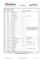
Page 21: ...I 61 P0_17 AX_SPIM_SDI__MII_TXEN I 60 P0_18 AX_SPIM_SDO__MII_CLK I 81 P0_4 AX_SPIS_CS0 __MII_TXD0__ SBDW_D0 O_1 74 P2_1 AX_SPIS_CS1 __MII_TXD1__ SBDW_D1 O_1 79 P0_6 AX_SPIS_CS2 O_1 65 P2_8 AX_SPIS_MB0...

Page 22: ...RMII_REF_CLK O_0 91 P1_9 RMII_RXD0 I 90 P1_10 RMII_RXD1 I 89 P1_14 RMII_RXER I 95 P1_0 RMII_TXD0 O_0 94 P1_1 RMII_TXD1 O_0 93 P1_4 RMII_TXEN O_0 57 P0_21 UC_DIP_0 I Apix Data Interface Suspend Mode En...

Page 23: ..._P1_21 I 36 P1_22 UC_P1_22 I 37 P1_23 UC_P1_23 I 38 P1_24 UC_P1_24 I 39 P1_25 UC_P1_25 I 52 P2_11 UC_P2_11 I 51 P2_12 UC_P2_12 I 50 P2_13 UC_P2_13 I 17 RESET UC_RESET_N I Hardware Reset 69 P2_4 UC_RES...

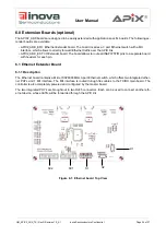
Page 24: ...ender board The board allows to route all INAP375T R pins to a separate board with headers for each pin 6 1 Ethernet Extender Board 6 1 1 Description The Ethernet board contains a Micrel KSZ8893MQL 3...

Page 25: ...need to be connected through specific cables provided with the kit to the master boards Dip Switch S1 needs to be set to 00011000 8 1 Master board connector Ethernet board connector Description SV1 SV...

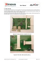
Page 26: ...ova semiconductors ships one 20pin cable one 16 pin cable and two 20pin white flex cables Also included are additional bolts acting as stand and distance bolts Start with connecting the grey power and...

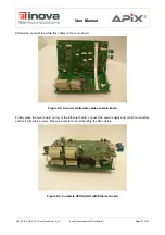
Page 27: ...hite flex cables to the main board Figure 6 4 Connect white data cables to main board Finally place the main board on top of the Ethernet board connect the power supply and control connectors and fix...

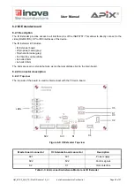
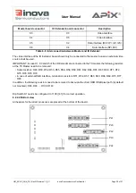
Page 28: ...n power cable grey 16pin control cabe grey 5x 20pin flex cable white 4x bolts 20mm 4x bolts 30mm The bolts are used as stands but also as mechanical distance bolt to the main board 6 2 2 Connector des...

Page 29: ...R78 R79 In case of external RGB interface termination resistors R51 R54 R57 R60 R63 R66 R69 R73 R77 R80 In addition the following resistors need to be removed to decouple the direct HDMI RGB pixel pa...

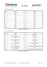
Page 30: ...PX4 4 GND 14 GND 5 PX18 15 PX3 6 GND 16 GND 7 PX17 17 PX2 8 GND 18 GND 9 PX16 19 PX1 10 GND 20 GND Table 6 4 Pin Header PL1 Pin Signal Pin Signal 1 SPI_S_CS2 11 I2S_DATA 2 GND 12 GND 3 SPI_S_RW MII_TX...

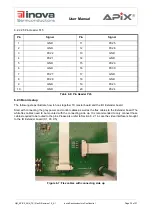
Page 31: ...GND 16 PX13 7 PX12 17 GND 8 PX11 18 GND 9 GND 19 PX8 10 GND 20 PX7 Table 6 6 Pin Header PL3 Pin Signal Pin Signal 1 GND 11 SPI_S_SDO 2 SPI_M_SDO MII_CLK 12 SPI_S_SDI 3 GND 13 GND 4 SPI_M_SDI MII_TXEN...

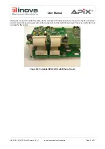
Page 32: ...s to the Extender board The white flex cables need to be mounted with the connecting side up It is recommended to only connect those cables required to be routed to the pins Please also refer to Secti...

Page 33: ...Afterwards connect the white flex cables to the main board Finally place the main board on top of the Ethernet board connect the power supply and control connectors and fix it with the 4 screws Pleas...

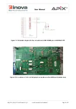
Page 34: ...g up and enabling the transmitter The trans mitter input clock may also be applied after power up however the use of the PWR DOWN pin is required as described in the Transmitter Input Clock section se...

Page 35: ...2_A1 Inova Semiconductors Confidential Page 35 of 37 User Manual Figure 7 9 Schematic diagram for the connections to PWR DOWN pin on ADK INAP 375T Figure 7 10 Locations of SJ1 and SJ2 jumper connectio...

Page 36: ...AP375T R Datasheets Inova Semiconductors GmbH 3 INAP375T R Usermanual Inova Semiconductors GmbH Ordering Code Description APIX2_ADK_TX APIX2 ADK Transmitter Demonstration Board with HSD Connector APIX...
Page 37: ...of others Inova Semiconductors products are not designed intended or authorized for use as components in systems to support or sustain life or for any other application in which the failure of the pro...

Reviews: