危
险
!
CAUTION
Vacuum
pumping
-Do use Nitrogen.
Air tight procedure
Completion
of
Ref
.
Piping
Repairing
of
Leakage
Part
Check
of
Pressure
Decrease
Applying
Nitrogen
Gas
Pass
Procedure
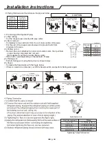
Connect the gauge manifold using charging hoses with a nitrogen
cylinder to the check joints of the liquid line and the gas line stop valves
.
Perform the air
-
tight test
.
Don
'
t
open
the gas line stop valves
.
Apply nitrogen gas pressure of
psi (
MPa
.
550
3.8
)
Check
for
any
gas
leakage
at
the
flare
nut connections
,
or brazed parts
by gas leak detector or foaming agent
.
Gas pressure doesn’t decrease is OK.
After
the
air
tight
test
,
release
nitrogen gas.
6. Vacuum
pumping
and
charge
refrigerant
Vacuum
pump
-0.101MPa
(-760 mmHg)
manifold gauge
Charge hose
(for R410A)
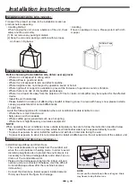
Piping insulation procedure
Connect pipes using different-diameter joint
Insulation
(
)
field-supplied
(
6
)
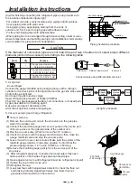
After finishing connecting the refrigerant pipes, keep it warm with
the insulation material like figure right.
·
For outdoor unit side, surely insulate every piping including valves.
·
Cover piping joints with pipe cover.
·
Using piping tape, apply taping starting from the entry of
outdoor unit. Fix the end of piping tape with adhesive tape.
-
Fix the end of piping tape with adhesive tape.
-
When piping has to be arranged through above ceiling, closet or area
where temperature and humidity are high, wind additional commercially
sold insulation for prevention of condensation.
Clamp(field-supplied)
Insulation (field-supplied)
Refrigerant pipe
(field-supplied)
(1) Remove the service port cap of the stop valve on the gas pipe
side of the outdoor unit.
(2) Connect the manifold gauge and vacuum pump to the service port
of the stop valve on the gas pipe side of the outdoor unit.
(3) Run the vacuum pump. (Work for more than 15 minutes.)
(4) Check the vacuum with the gauge manifold valve, then close the
gauge manifold valve and stop the vacuum pump.
(5) Leave it as is for one or two minutes. Make sure the pointer of the
manifold gauge remains in the same position. Confirm that the
pressure gauge shows -14.7 psi(-0.101MPa or -760mHg).
(6)Remove the manifold gauge quickly from the service port of the
stop valve.
(7) After refrigerant pipes are connected and evacuated, fully open
all stop valves on both sides of gas pipe and liquid pipe.
(8) Open adjusted valve to add refrigerant
(
must be refrigerant
is
liquid
).
(9) Tighten the cap to the service port .
(10) Retighten the cap.
(11) Leak test foam with halogen leak detector to check the flare nut
and brazing Carolina Department leaks. Use foam that not
generate ammonia (NH3) in the reaction.
9
5.
Air
tight test
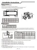
If the diameter of connection pipe does not match the port size of outdoor unit, select proper different-
diameter joints in the accessory according to the following table.
Name
Qty
Purpose
1
Change pipe diameter from
1/4(6.35) to 3/8(9.52)
1
Change pipe diameter from
3/8(9.52) to 5/8(15.88)
1
Change pipe diameter from
3/8(9.52) to 1/2(12.7) mm
Outdoor unit
Different-diameter joint
indoor unit
Installation instructions
Summary of Contents for 18K
Page 17: ......


