


Diagnostic Tool Controls
DISPLAY FUNCTIONS
8
3100j
7.
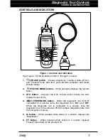
UP button
– When in MENU mode, scrolls UP through the
menu and submenu selection options. When LINKED to a vehicle,
scrolls UP through the current display screen to display any
additional data.
8.
ENTER button
- When in Menu mode, confirms the selected
option or value.
9.
DOWN button
- When in MENU mode, scrolls DOWN through
the menu and submenu selection options. When retrieving and
viewing DTCs, scrolls down through the current display screen to
display any additional data.
10. GREEN LED
- Indicates that all engine systems are running
normally (all Monitors on the vehicle are active and performing their
diagnostic testing, and no DTCs are present).
11. YELLOW LED
- Indicates there is a possible problem. A “Pending”
DTC is present and/or some of the vehicle’s emission monitors have
not run their diagnostic testing.
12. RED LED
- Indicates there is a problem in one or more of the
vehicle’s systems. The red LED is also used to show that DTC(s)
are present. DTCs are shown on the diagnostic tool’s LCD display.
In this case, the Malfunction Indicator (“Check Engine”) lamp on the
vehicle’s instrument panel will light steady on.
13. LCD Display
- Displays settings Menu and submenus, test results,
diagnostic tool functions and Monitor status information. See
DISPLAY FUNCTIONS, on next page, for more details.
14. CABLE
- Connects the diagnostic tool to the vehicle’s Data Link
Connector (DLC).
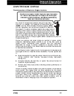
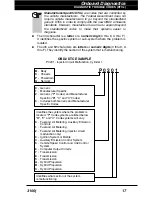
DISPLAY FUNCTIONS
Figure 2. Display Functions
See Figure 2 for the locations of items 1 through 13, below.
1. I/M MONITOR STATUS field
- Identifies the I/M Monitor status area.
4
3
2
5
8
6
7
1
11
12
13
9
10
14
Summary of Contents for 3100j
Page 1: ......
Page 104: ...Notes 102 3100j ...
Page 105: ...Notes 3100j 103 ...
Page 106: ...Notes 104 3100j ...
Page 108: ......