12
Functions and features
Power supply stations
Chapter 4
Functions and features
4.1
Controlling the Outputs
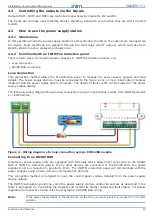
The power-supply outputs can be controlled locally, via the on-board inputs B1, B2 and B3 or remotely, via
the RS485 BUS of an INIM Fire detection panel.
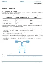
The outputs follow the "OR" logic of the status of their command inputs, refer to the following Table.
You can define the standby status of each output using the Booster option in the programming menu (refer
to
paragraph 10.1.1 Setting up the Booster parameters
):
1. Standby-ON
Under these circumstances, there will be 24V
(ON) across the terminal when the output is in standby
status and 0V
(OFF) when the output activates. This is the setting at default.
2. Standby-OFF
Under these circumstances, there will be 0V
(ON) across the terminal when the output is in standby
status and 24V
(OFF) when the output activates.
You can also classify the output as monostable, in this way, it will be possible to define the output activation
time (ON Time). Once the set activation time expires, the output will restore to standby status
automatically but cannot be re-activated until the cause of activation clears.
If the activation time is not defined (“--”), the output will restore to standby status only when the cause of
activation clears.
Figure 3 - Output activation
Note:
The outputs will be blocked automatically when you insert the programming jumper.
Command input
Remote command via RS485 BUS
Output
Open (standby)
OFF (default)
Standby
Open (standby)
ON
Active
Closed (active - default)
OFF (default)
Active
Closed (active - default)
ON
Active
OR
Station
inputs
RS485
BUS
OUTPUT
ACTIVE
Standby-ON
Standby-OFF
0V
24V


