INIM Electronics Previdia Compact Manual Download Page 7

Configuration manual

Configuration

7

Chapter 2

Configuration

2.1

First startup

Once the installation and cabling procedures have been completed (refer to the Installation Manual of the Previdia
Compact system) the system is ready for first startup.

In the case of first startup and after having performed the procedure to set the factory data, it is necessary to enter the
unlocking code:

This is a code printed on the label affixed to the cardboard box containing the control panel. Alternatively, it can be found
at the following Internet address (the serial number of the control panel will be requested, once provided the unlocking
code will be supplied):

https://service-previdia.inimcloud.com

After entering the unlocking code, selection of the control panel languages is required (a mandatory main language and
an optional second language).

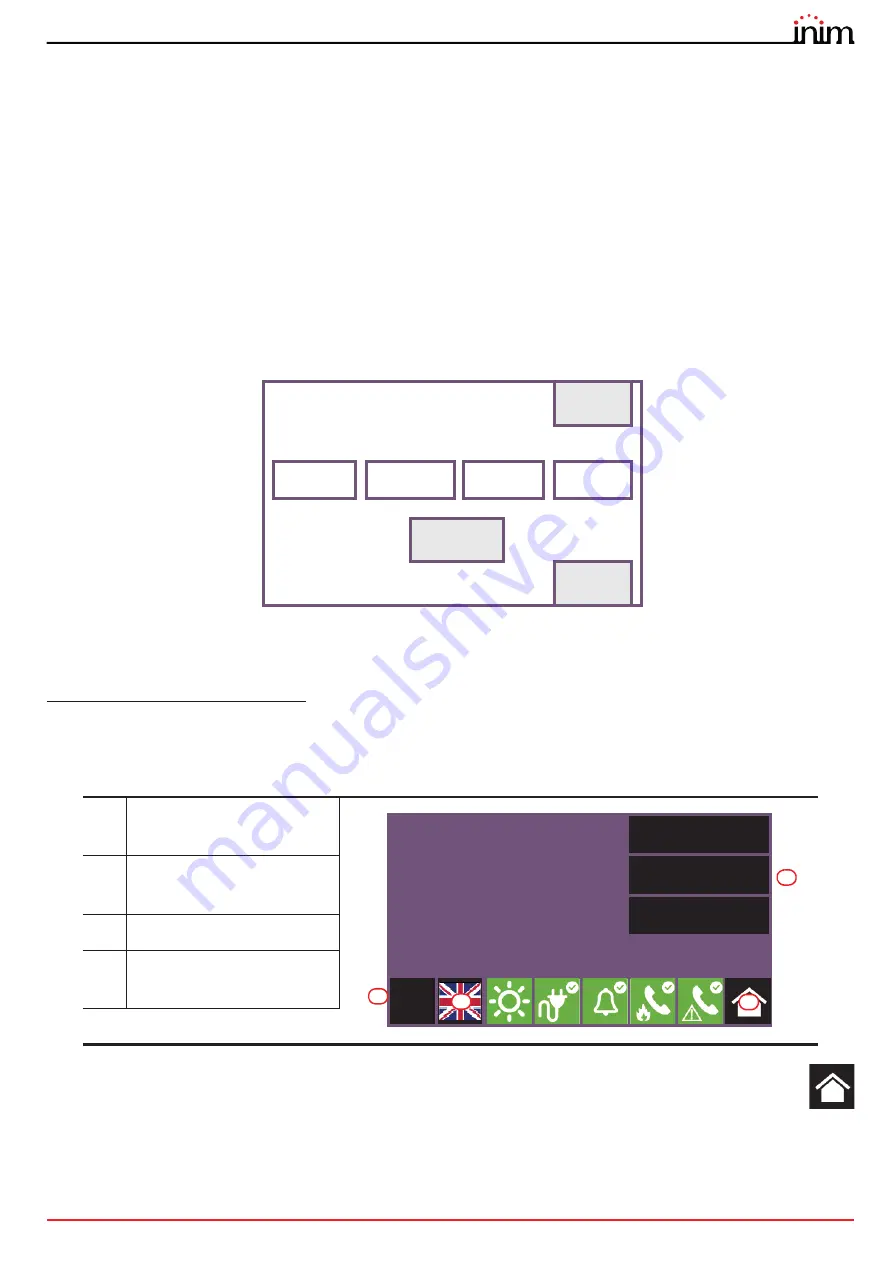
The control panel screen will be as follows:

In the case of faults or other types of events, the latter will be shown on the display. You can retrieve the home
screen at any time by tapping on the respective icon on the status bar

 [C]

.

In order to configure the Previdia control panel it is necessary to work through the following procedure:

1.

Access programming (

paragraph 2.2

)

2.

Access the configuration menu (

paragraph 2.3

)

[A]

Buttons to access the events 

log, system status and 

programming.

[B]

Status bar (always present) 

shows essential information 

regarding the system.

[C]

“Home” button

[D]

Button for changing the 

language of the control panel, if 

a second language is provided

Please enter the code
printed on the control panel box

SHOW

(also on https://service-previdia.inimcloud.com)

1 2 3 4 5

1 2 3 4 5

1 2 3 4 5

1 2 3 4 5

OK

ESC

Log

System status

Programming

01/01/2020 18:23

L:1

D

C

A

B

Summary of Contents for Previdia Compact

Page 1: ...FIGURATION COMMISSIONING AND MAINTENANCE EN 54 2 EN 54 4 EN 54 21 EN 12094 1 ANALOG ADDRESSABLE FIRE ALARM CONTROL PANEL EXTINGUISHANT SYSTEM CONTROL PANEL ALARM TRANSMISSION AND FAULT WARNING ROUTING...

Page 2: ...en goods or claims by any other party caused by defective products or otherwise arising from the incorrect or otherwise improper installation or use of this product This warranty applies only to defec...

Page 3: ...figuring the Hornet network 13 3 5 Configuring the loops 13 3 6 SD card functions 16 3 7 Configuring the terminals 16 3 8 Configuring the users 17 3 9 Configuring the communicator 17 3 10 Configuring...

Page 4: ...4 Table of contents Fire detection and extinguishant system...

Page 5: ...scribes the procedures for the configuration commissioning and maintenance of the Previdia Compact fire detection system 1 2 1 Graphic conventions Following are the graphic conventions used in this ma...

Page 6: ...ctivate alarm signalling when an early warning condition is running Level 2 Authorized users this access level is for the system supervisors and is for authorized personnel who are adequately instruct...

Page 7: ...languages is required a mandatory main language and an optional second language The control panel screen will be as follows In the case of faults or other types of events the latter will be shown on t...

Page 8: ...cess the programming phase of the Previdia control panel it is necessary to work through the following procedure 1 Insert the programming jumper see opposite D 2 Press the Programming button on the st...

Page 9: ...to paragraph 4 2 Loop points refer to paragraph 4 1 Icon Function buttons Display Access to the configuration of the general parameters of the control panel Refer to paragraph 3 1 Access to the config...

Page 10: ...onfiguration data on the Previdia Compact control panel can be done in two ways By selecting the Factory data option from the programming menu refer to paragraph 2 2 Using the buttons available on the...

Page 11: ...tivated disables the control panel buzzer Direct alarm on second pre alarm option that if activated generates an alarm signal as soon as two detectors go into pre alarm status regardless of the zone t...

Page 12: ...Installer Property option If activated the installer reserves the management of accesses to the system by the Cloud If not activated this property is assigned to the first user enrolled 4 Press the E...

Page 13: ...e Esc and Set buttons will allow you to exit the section without changing the programming or saving it 3 5 Configuring the loops The operations for the configuration of the loops and the devices conne...

Page 14: ...n in the columns on the left A and the newly detected configuration in the columns on the right B Positions in which changes have not been detected will be outlined in green Changes will be indicated...

Page 15: ...in configuration The lower part C provides the following buttons Loop reset button to reset the loop and reassess its status In the event of a Loop open fault it will be necessary to tap on this butt...

Page 16: ...SD card and there is the file Logo bmp file is the image contained in it 260x222 pixel will be shown on the stand by screen The Esc and Set buttons will allow you to exit the section without changing...

Page 17: ...t control panels are supplied at default with the first 4 codes already pre set 3 9 Configuring the communicator To set the network parameters you must first enter the control panel programming phase...

Page 18: ...rent from that detected by the control panel the appropriate icon inside the control panel configuration screen will change status and appear in yellow 3 9 1 Configuration of the PREVIDIA C COM module...

Page 19: ...w the system can be configured so that the extinction channel is activated when there are at least two alarms in zone 2 3 10 3Extinction input The Inputs button C will allow you to configure the contr...

Page 20: ...disables the programmed inputs for manual activation of the extinction procedure Disab Man Extinc option 4 23 Manual only mode of EN 12094 1 disables the automatic activation of the extinction proced...

Reviews: