47 / 92
1)
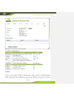
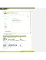
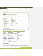
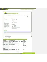
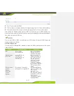
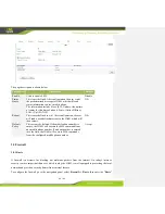
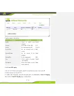
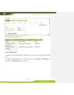
Set the Modbus type: RTU and TCP are available.
2)
Under RTU type, configure the slave address of each PLC, namely the ‘Modbus ID.’ It may be
assigned a value from 1 to 247. Under TCP mode, configure the IP address and port number of
PLC.
3)
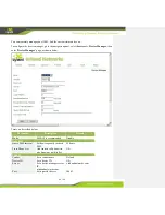
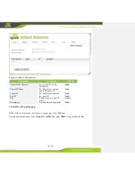
Configure name of the PLC, using a maximal length of 16 bytes. Specific PLC name will be
used in SMS.
4)
PLC Authen: set authentication password to ensure the PLC is tamper-evident. As the password
is saved to register 40100-40103, the register 40100-40103 cannot be used when configuring
register.
5)
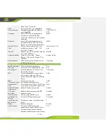
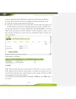
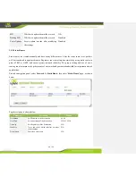
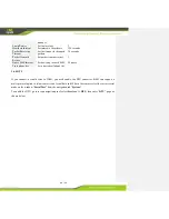
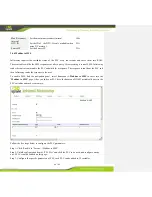
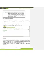
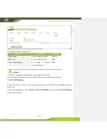
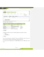
New Variables:
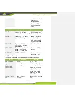
First column is register address (from 1). 0xxxxx is for discrete inputs. 1xxxxx is for a
coil. 3xxxxx is for the incoming register, and 4xxxxx indicates a holding register.
Second column is the variable type, supporting BIT, WORD, DWORD, FLOAT, INT16,
INT32 and INT64.
Third column is the units of variable with maximum length of 8 bytes. This value will
appear in SMS, and you can leave this field empty. The unit of BIT variables should be
configured according to HH/LL format, HH represents the corresponding unit of “1,” LL
represents the corresponding unit of “0.” The units of other types of variables will appear
directly in SMS.
Fourth column is register name with a maximum length of eight bytes. Users can define
names for each variable and this field must be filled. The variable address will be replaced
by variable name in SMS.
PLC ID in IG601 cannot be repeated, neither can PLC names.
Variable names cannot be repeated in one PLC variable list.
Each PLC should be defined with ID, name and at least one variable.
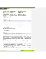
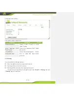
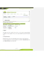
Click “Add” to add new variables.
Step 4: Repeat step 3 and add more PLCs.
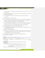
Step 5: Click <Apply> button, save and apply the new configuration.

