


Installation
20
RT-SVX46C-EN
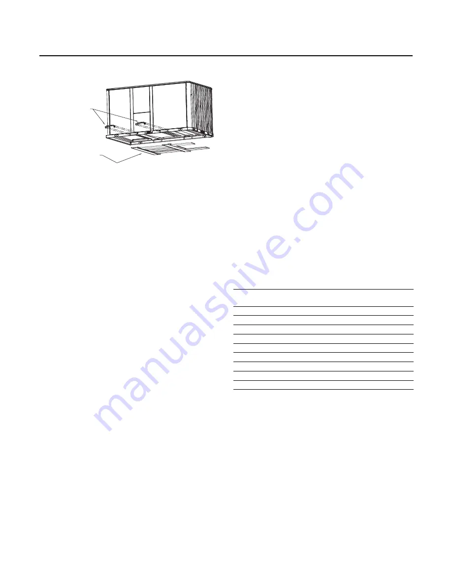
6. Lift the unit enough to allow the removal of base fork
pocket protection components as shown in the
following figure.
7.
Down flow units; align the base rail of the unit with the
curb rail while lowering the unit onto the curb. Make
sure that the gasket on the curb is not damaged while
positioning the unit.
General Unit Requirements
The checklist listed below is a summary of the steps
required to successfully install a commercial unit. This
checklist is intended to acquaint the installing personnel
with what is required in the installation process. It does not
replace the detailed instructions called out in the
applicable sections of this manual.
•
Check the unit for shipping damage and material
shortage; file a freight claim and notify appropriate
sales representative.
•
Verify correct model, options and voltage from unit
nameplate.
•
Verify that the installation location of the unit will
provide the required clearance for proper operation.
•
If applicable, assemble and install the roof curb. Refer
to the latest edition of the curb installers guide that
ships with each curb kit.
•
Fabricate and install ductwork; secure ductwork to
curb.
•
If applicable, install pitch pocket for power supply
through building roof.
•
Rigging the unit.
•
Set the unit onto the curb; check for levelness.
•
Ensure unit-to-curb seal is tight and without buckles or
cracks.
•
Install and connect a condensate drain line to the
evaporator drain connection.
Note:
Condensate Overflow Switch (if equipped) will not
work if unit is not leveled properly.
Factory Installed Economizer
•
Ensure the economizer has been pulled out into the
operating position. Refer to the economizer installers
guide for proper position and setup.
•
Install all access panels.
Temperature Limit Switch Usage for Gas
Heat Units
Units are factory shipped in the down flow discharge
configuration but can be field converted to a horizontal
discharge configuration. Some, but not all units require a
different TCO1 limit switch, which is attached to the
combustion blower motor if horizontal discharge
configuration is used.
Note:
The following units require a limit switch change
out for horizontal discharge. The additional limit
switch is shipped attached to the combustion
blower housing:YZC036E**(M,Y),YZC048F**(L,X)
direct drive ID motor.
If any of the aforementioned units are installed in the down
flow discharge configuration, remove the additionalTCO1
limit switch from the combustion blower motor and
discard.
Horizontal Discharge Conversion
Note:
3 ton unit supply cover to supply opening and
return cover to return opening. 4 and 5 ton unit
return cover to supply opening and supply cover to
return opening.
Supplies needed by installer for conversion: 3 oz. tube of
high temperature RTV sealant. (500°F / 260°C: similar to
Dow Corning 736)
Important:
Failure to use recommended sealant could
result in unit performance loss.
If a unit is to be converted to a horizontal discharge, the
following conversion must be performed:
1.
Remove RETURN and SUPPLY duct covers.
Figure 14.
Fork pockets - all units
Remove 2
Fork Lift
Brackets
Remove 2 Metal Runners
and 3 Wooden Boards
Table 3.
TC01 tripping values
Unit Model
TCO1 Tripping Values -
Downflow/ Horizontal
YZC036E**(L,X)
190F°
YZC036E**(M,Y)
170°F /220°F
YZC036E**(H,Z)
220°F
YZC048F**(L,X)
145°F /155°F
YZC048F**(M,Y)
170°F
YZC048F**(H,Z)
220°F
YZC060E**(L,X)
140°F
YZC060E**(M,Y)
170°F
YZC060E**(H,Z)
170°F


