


6
16575185_ed3
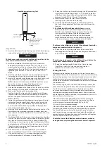
Needle Bearing Inserting Tool
Shoulder to
regulate depth
15°
Pilot to fit I.D. of bearing.
Length of pilot to be
approximately 1/8''
less than length of
bearing
(Dwg. TPD786)
11. Insert the Bit Holder (77) into the large end of the Clutch Housing
and push the output end through the Clutch Housing Bearing.
NOTICE
The following step has parts with a left-hand thread. Rotate the
components counterclockwise to tighten them.
12. Install the assembled Clutch Housing (75) over the clutch
components and thread it onto the Gear Case. Using a 1 1/16”
wrench on the flats of the Gear Case and the Clutch Housing
Spanner Wrench (Part No. TRH-478) in the clutch housing slot,
tighten the joint between 15 and 20 ft.-lbs. (20 and 27 Nm)
torque.
13. Invert the assembled tool in the vise jaws and lightly grasp the
flats on the Gear Case with the inlet end of the tool upward.
14. Insert a 5/8” dowel through the opening in the Back Cap (5), and
using the dowel as an alignment device, install the three
Muffler Elements (7) in the cavity of the Back Cap. Make certain
the notches in the outer edge of the Elements fit over
the memory chip pocket in the bottom of the Cap.
15. If the tool is equipped with a Memory Chip (8), install it (with the
leads entering first) in the pocket at the bottom of the Back Cap.
16. Make certain the tab on the inside edge of the
Back Cap Gasket (6) is aligned with the pocket for the Memory
Chip and install the Gasket, metal face leading, in the recess of
the Back Cap against the face with the cavity containing the
Muffler Elements.
17. Position the gasket end of the alignment dowel against the inlet
hub on the Motor Housing. Align the flats on the Cap with the
flats on the Housing. Orient the Back Cap to clear the Reverse
Lever (13) and slide the Back Cap Assembly off the alignment
dowel and onto the Motor Housing.
18. Insert the Push Rod (28) into the central hole in the inlet hub. The
Rod will enter the assembled motor and disappear from view
when released. Install the Shutoff Valve (14), small end first, in the
same opening.
19. The Exhaust Diffuser (9) has one slot that is longer than the other
five slots. The Back Cap has a short, molded stud projecting from
the inlet end. Place the Exhaust Diffuser against the Back Cap
with the long slot encircling the molded stud. Rotate the Diffuser
counterclockwise until the wall of the slot stops against the stud.
The exhaust ports are now in the full open position which will
provide maximum free speed.
20. If the Inlet Screen (12) required replacement, use a wooden
dowel to carefully push a new one into the Inlet Bushing (10).
21. If the Inlet Bushing Seal (11) is nicked or damaged, carefully
install a new one over the threads of the Inlet Bushing.
22. Thread the Inlet Bushing Assembly through the Diffuser and Back
Cap into the Motor Housing. Using a 1-3/16” wrench on the flats
of the Back Cap to keep it from turning, tighten the Inlet Bushing
between 15 and 20 ft.-lbs. (20 and 27 Nm) torque.
23. Remove the tool from the vise jaws and install the
Housing Grip (85) over the Clutch Housing.
24. Install the Grip Retaining Ring (88) in the external groove on
the Clutch Housing ahead of the Grip to retain the Grip on the
Housing.
25.
For Models with Quick Release Bit Holders
, place the
Bit Retaining Ball (78) in the hole through the wall of the
Bit Holder and slide the Bit Retaining Sleeve (80), large end
trailing, onto the Bit Holder. Slide the Retaining Sleeve
Spring (81) and Spring Seat (82) onto the Bit Holder and
secure the components by installing the Retaining Ring (83)
in the external groove at the output end of the Bit Holder.
NOTICE
The thread in the following step is a left-hand thread. Rotate the
component counterclockwise to tighten it.
26. Thread the Clutch Adjusting Hole Cover (89) onto the Clutch
Housing against the Housing Grip and hand tighten it between 2
and 6 ft.-lbs. (3 and 8 Nm) torque.
NOTICE
The following step has parts with a left-hand thread. Rotate the
components counterclockwise to tighten them.
27. Thread the Non-Rotating Bit Finder (84) or Clutch Housing
Cap (90) onto the Clutch Housing and hand tighten it
between 2 and 6 ft.-lbs. (3 and 8 Nm) torque.
Testing the Tool
Before placing the tool back in service, test the tool in a run down
application to determine if adjustments are necessary to satisfactorily
perform the operation. Since five interrelated adjustments can affect
tool performance, only experience, along with trial and error, can
dictate which adjustment or combination of adjustments will provide
the desired results.
The Clutch Spring (53 or 69), the clutch adjustment procedure, the
exhaust flow, the length of the Push Rod (28) and the length of the
Shutoff Valve (14) can individually or collectively have an effect
on torque and/or speed. Always try to make adjustments before
replacing or attempting to modify components. If adjustments are
unable to provide the desired torque, it may be necessary to install a
lighter or heavier Clutch Spring.
If the tool ratchets when operated but fails to shutoff, it may be
necessary to shorten the Push Rod. Only shorten the Push Rod in
small increments. Increments between 0.005” and 0.010”
(0.13 and 0.25 mm) are recommended.
If the tool stalls and does not shutoff, runs slower than normal or has
low power, the Shutoff Valve may require lengthening. To lengthen
the Shutoff Valve, grasp the stem between two pieces of rubber
or other non-slip, non marring material and rotate the molded nut
counterclockwise. Rotating the nut one half revolution will lengthen
the Valve approximately 0.009” (0.23 mm).
Should the stem of the Valve become bent, marred, nicked or
damaged in any way during the adjustment process, replace it.


