


16575185_ed3
5
10.
For Series QS1P28
, lubricate the Planet Gear Head Drive
Plate (31) with
Ingersoll Rand
No. 67 Grease and install it
on the shafts of the Planet Gear Frame Assembly.
11. Install the Gear Head Spacer (30) against the Gears or Drive Plate
and secure the assembly by using snap ring pliers to install the
remaining Gear Retainer in the internal groove at the motor end
of the Gear Case.
Assembly of the Adjustable Cushion Clutch
1. Insert the small end of the Clutch Shaft (62) into the end of the
Cam Jaw (64) having the large opening and slide the Shaft about
half way into the Jaw.
2. Drop the twelve Clutch Balls (63) into the Cam Jaw forming a ring
around the Clutch Shaft.
3. Lay a bead of
Ingersoll Rand
No. 28 Grease, approximately
2 to 3 cc, on top of the Clutch Balls and then bring the Clutch
Shaft and Cam Jaw together capturing the Balls between them.
4. While holding the Shaft and Jaw together, slide the Clutch Cam
Ball Driver (65), large end leading, onto the Clutch Shaft until it is
against the Cam Jaw.
5. Rotate the Driver to align the large hole through one wall of
the Driver with the comparable size opening of the cross hole
through the Clutch Shaft. Push the Clutch Cam Ball Driver
Retaining Pin (67) into the hole to lock the Driver in position on
the Clutch Shaft.
6. Apply a coating of
Ingersoll Rand
No. 28 Grease to each of the
eleven Clutch Cam Balls (66).
7. Holding the assembled Clutch Shaft with the Clutch Cam Ball
Driver upward, insert a lubricated Ball into each of the eleven ball
pockets in the Driver.
8. Slide the Cam Ball Seat (68), large end leading, onto the Shaft
against the Balls. Follow with the Clutch Spring (69),
Spring Seat (70), Thrust Bearing (71) and the Clutch Adjusting
Nut Washer (72) with the smooth face leading.
9. Thread the Clutch Adjusting Nut (73), smooth face trailing, onto
the Clutch Shaft.
10. Insert the tip of a #1 Phillips Head Screwdriver into the
adjustment opening between the Clutch Adjusting Nut and
the Clutch Adjusting Nut Washer. Rotate the screwdriver
counterclockwise and thread the Adjustment Nut onto the
Clutch Shaft until the external groove for the
Clutch Adjusting Nut Stop (74) is visible.
11. Install the Nut Stop in the groove.
Assembly of the Adjustable Shutoff Clutch
1. Lightly grasp the Clutch Shaft (46) in leather-covered or
copper-covered vise jaws with the large end upward.
2. Insert the Automatic Shutoff Plunger Return Spring (43) into the
central opening in the large end of the Clutch Shaft. Use a 1/8”
dowel to push the Spring below the cross hole for the Automatic
Shutoff Pin (44).
3. Insert the Automatic Shutoff Pin Spring (45) in the end hole of
the Automatic Shutoff Pin opposite the pointed end. Rotate the
Spring a little to keep it in the hole.
4. Drip one or two drops of
Ingersoll Rand
No. 10 Oil into the
central hole with the Plunger Return Spring.
5. Position the Shutoff Pin, Spring leading, in the cross hole on the
large end of the Clutch Shaft with the hole in the Shutoff Pin
aligned with the central hole containing the Return Spring.
6. Push on the pointed end of the Shutoff Pin to depress the
Spring while inserting the Automatic Shutoff Plunger (42) into
the central opening with the Return Spring. The smaller center
portion of the Shutoff Plunger will allow the Shutoff Pin to spring
outward and capture the components within the Clutch Shaft
when properly positioned.
7. Remove the Clutch Shaft from the vise jaws.
8. Insert the small end of the Clutch Shaft into the end of the Cam
Jaw (48) having the large opening and slide the Shaft about half
way into the Jaw.
9. Drop the twelve Clutch Balls (47) into the Cam Jaw forming a ring
around the Clutch Shaft.
10. Lay a bead of
Ingersoll Rand
No. 28 Grease, approximately
2 to 3 cc, on top of the Clutch Balls and then bring the Clutch
Shaft and Cam Jaw together capturing the Balls between them.
11. While holding the Shaft and Jaw together, slide the Clutch Cam
Ball Driver (49), large end leading, onto the Clutch Shaft until it is
against the Cam Jaw.
12. Rotate the Driver to align the large hole through one wall of
the Driver with the comparable size opening of the cross hole
through the Clutch Shaft. Push the Clutch Cam Ball Driver
Retaining Pin (51) into the hole to lock the Driver in position on
the Clutch Shaft.
13. Apply a coating of
Ingersoll Rand
No. 28 Grease to each of the
three Clutch Cam Balls (50).
14. Holding the assembled Clutch Shaft with the Clutch Cam Ball
Driver upward, insert a lubricated Ball into each of the three ball
slots in the Driver.
15. Slide the Cam Ball Seat (52), large end leading, onto the Shaft
against the Balls. Follow with the Clutch Spring (53),
Spring Seat (54), Thrust Bearing (55) and the Clutch Adjusting
Nut Washer (56) with the smooth face leading.
16. Thread the Clutch Adjusting Nut (57), smooth face trailing, onto
the Clutch Shaft.
17. Insert the tip of a #1 Phillips Head Screwdriver into the
adjustment opening between the Clutch Adjusting Nut and
the Clutch Adjusting Nut Washer. Rotate the screwdriver
counterclockwise and thread the Adjustment Nut onto the Clutch
Shaft until the external groove for the Clutch Adjusting
Nut Stop (58) is visible.
18. Install the Nut Stop in the groove.
Assembly of the Tool
1. Lightly grasp the flats at the inlet end of the Motor Housing (1) in
leather-covered or copper-covered vise jaws with the motor bore
upward.
2. Grasp the spline of the Rotor (21) in the assembled motor and
after aligning the End Plate Alignment Pin (24) with the internal
notch in the motor end of the housing bore, insert the assembled
motor into the Motor Housing. Make certain the motor is far
enough into the Housing to have the undercut below the internal
housing thread visible.
3. Lubricate the Motor Seal (26) with O-Ring lubricant and install
it around the Front End Plate (23) and into the undercut in the
Housing.
4. Align the tab of the Motor Clamp Washer (27) with the internal
notch in the Housing and install it over the rotor hub and End
Plate Alignment Pin against the Motor Seal. Make certain the Pin
enters the hole in the Washer and the Washer is flat against the
Seal.
5. Apply some
Ingersoll Rand
No. 67 Grease to the spline on the
rotor shaft.
6. Thread the assembled Gear Case (37), output spindle trailing, into
the Motor Housing and using a 1-1/16” wrench, tighten the joint
between 15 and 20 ft.-lbs. (20 and 27 Nm) torque.
7. Place the narrow end of the Clutch Return Spring (40 or 59) in the
Gear Case against the inner race of the Spindle Bearing (38).
8. Place the hex. drive end of the Clutch Input Driver (41 or 60)
on the Spring and compress the Spring until the hex. on the
Driver enters the hex. recess on the Spindle Assembly (36). While
holding the Driver in position, engage the raised bar on the face
of the Driver with the jaw of the Cam Jaw (48 or 64).
9. If the Clutch Housing Bearing (76) was removed, stand the Clutch
Housing (75) on the table of an arbor press with the smaller,
externally threaded end downward.
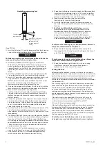
10. Using a Needle Bearing Inserting Tool as shown in Dwg. TPD786
with a 0.030” (0.76 mm) thick washer that clears the inner bore
and outer edge of the Bearing inserted between the Bearing
and stop surface on the tool, press the Bearing into the Clutch
Housing. The trailing end of the Bearing must be between 0.025”
and 0.035” (0.63 and 0.89 mm) below the face of the bore into
which the Bearing is pressed.


