9
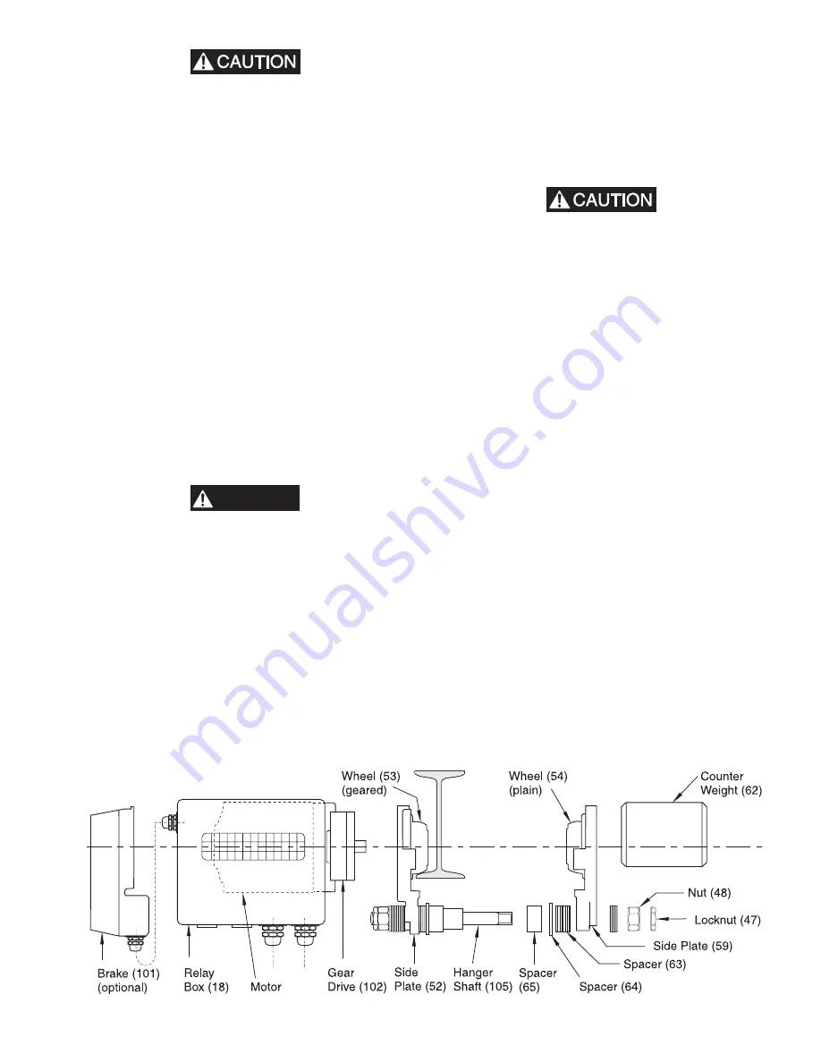
• Total clearance between wheel flanges (53 and 54) and
beam flange must not exceed 0.078 in. (2 mm). At least one
spacer (63) must always be placed between the side plate and
the nut (48). Torque nut (48) in accordance with Table 4.
Install locknut (47) hand tight, then tighten with a wrench
an additional 1/4 or 1/2 of a rotation.
• Replace locknut (47) with a new one after each use. Do not
reuse locknuts.
The counterweight (62) is bolted to the side plate which has the
plain wheels (54). The gear assembly (102) with the relay box
(18) is attached to the side plate which has the geared wheels
(53). A brake assembly (101) can be retrofitted to all motorized
trolleys.
1.
The safe working load (SWL) of the trolley should be
checked first. Refer to trolley capacity information in
“SPECIFICATIONS” section.
2.
Spacers (63) are to be placed on the inside of the two side
plates, to suit the beam flange width. There should be an
equal number of spacers (63) on each side of the hanger
shaft. Remaining spacers should be equally placed on the
hanger shaft on the outside of side plates.
3.
Bolt the counterweight (62) to the outside of the side plate.
4.
The voltage should be checked.
5.
For the electrical connections: refer to electrical schematic.
6.
Verify beam/rail stops are securely installed.
Electrical Equipment
WARNING
• Electrical installation should be performed by licensed
electricians in accordance with the latest edition of the
National Electrical Code (ANAI/NFPA 70) and any
applicable local, state and national electrical codes and
ordinances.
• Never install two wires into the same terminal port.
For QMT50 and QMT150 trolleys, the supply cable should be
AWG-14 and for QMT300 trolleys AWG-12. The electrical
supply must have branch circuit protection in accordance with
National Electrical Codes. The supply cable wires must be
connected to terminals L1, L2, L3 and PE yellow/green (ground-
earth) in the trolley control assembly.
The control voltage is 42 volts (optional 110 volts) which is
produced by a built-in transformer. The brake assembly, if
equipped, is connected in parallel with the motor (refer to wiring
drawings).
Power Connection
Power Supply conductors must be sized in accordance with NEC
310-15(b) specifications.
Pendant Connection
For four button control pendants, feed pendant cable through
wire connector and into the relay box. Separate and connect
wires 1, 2, 3, 4, 41, 42, 43 and 50 (8 wires) to similarly marked
ports on the lower side of the terminal strip.
• Before connection of the electric chain hoist and/or trolley,
check to ensure that the voltage specified on the nameplate
matches the supply voltage.
After installation, the trolley should be connected by a licensed
electrician who is knowledgeable with NEC article 430 and
local regulations. Ensure that the voltage and frequency of the
electrical supply correspond with the data stamped on the trolley
nameplate before connecting the trolley.
In addition, the following points are of primary importance
when installing and connecting the trolley:
Restricted Ventilation will cause a trolley motor to operate at a
higher than desired temperature. Dirt, dust, chemicals, snow, oil,
etc. all can cause a problem. Avoid installing trolleys where air
flow will be restricted or excessive ambient temperatures may
be encountered.
Voltage Unbalance can cause excess temperature rise resulting
in premature trolley motor failure. Periodically check voltage.
Electrical Connections, if not tight and secure, will be a
continuous cause of trouble. During installation the electrician
must make sure that all electrical connections including the
ground connection are secure. Make sure all junction boxes and
switch enclosures are adequately sealed and protected for the
environmental conditions to be encountered.
To connect the trolley to the power supply, remove the electrical
cover plate which is located nearest the power supply and
pendant cable ports. Do not remove gear end cover. Connect the
power supply cable.
(Dwg. MHP0794)


