


20
18-CD37D1-2-EN
Installer’s Guide
▲
CAUTION
!
When the vent pipe is exposed to temperatures below
freezing, e.g., when it passes through unheated spaces,
etc., the pipe must be insulated with 1/2 inch (22.7 mm)
thick Armaflex-type insulation or equal.
If the space is heated sufficiently to prevent freezing, then
the insulation will not be required. If domestic water pipes
are not protected from freezing then the space meets the
condition of a heated space.
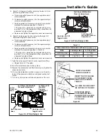
NOTE: If your furnace comes with a factory supplied 2" X
3" offset reducing coupling is used for 3" vent pipe instal-
lation, make sure the marking “TOP” is located on the top
side of the pipe.
The straight side of the coupling must be on bottom for
proper drainage of condensate. See Figure 27.
Horizontal Venting
NOTE:
Vent termination kit BAYAIR30AVENTA or BAYVENT200B
may be used in addition to the horizontal and vertical
termination options shown in the following figures.
For Canadian applications, venting systems must meet
ULC-S636 requirements.
HORIZONTAL VENTING
(Upflow/ Horizontal)
Figure 28
2" TO 3" COUPLING
FURNACE
VENT
OUTLET
FACTORY SUPPLIED ONLY
WITH THE FOLLOWING
MODELS:
ALL 100,000 BTUH UPFLOW
MODELS, ALL 120,000 BTUH
UPFLOW MODELS, AND ALL
DOWNFLOW MODELS
#CPL00938
Figure 30
Figure 27
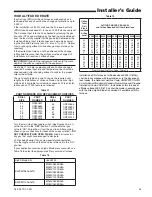
POSSIBLE CONFIGURATIONS FOR TWO PIPE VENTING SYSTEMS WHEN
BOTH TERMINATIONS ARE LOCATED IN THE SAME PRESSURE ZONE
6” Min.
24” Max
.
12” Min.
15” Max
.
9” Minimum
minimum from end
of exhaust pipe to
end of inlet pipe
6” Min.
24” Max
.
12” Min.
15” Max
.
9” Minimum
minimum from end
of exhaust pipe to
end of inlet pipe
6” Min.
24” Max
.
12” Min.
15” Max
.
9” Minimum
minimum from end
of exhaust pipe to
end of inlet pipe
6” Min.
24” Max
.
6” Min.
24” Max
.
ELBOW AND TEE
MUST BE AS CLOSE
TOGETHER
AS POSSIBLE


