


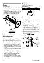


2. Press piston assembly into brake housing (207).
3. Install capscrews (201) in cover (202) and set on workbench with capscrew heads
down.
4. Grease and insert springs (203) in piston (204).
5. Install brake housing (207) assembly on cover (202) and capscrews (201).
6. Install friction disc housing (208) on capscrews (201).
7. Install bearing (217) and retainer ring (216) in brake cover (219).
8. Install oil seal (220) in brake cover (219) with lip toward the reduction gear end.
9. Install pinion shaft (237) through brake cover (219).
10. Install disc hub (211) on pinion shaft (237) and secure with retainer ring (214).
11. Install four friction discs (212) and three steel discs (213) on disc hub (211).
Alternate friction and steel discs beginning and ending with a friction disc.
12. Carefully install assembled brake cover (219) on friction disc housing (208).
Ensure tabs on friction discs (212) align with slots in disc housing (208).
13. Align capscrews (201) with capscrews holes in brake cover (219). Alternating on
a crossing pattern, tighten capscrews (201) half a turn at a time until tight. Refer
to “TORQUE CHART” on page 12 for torque requirements.
n
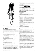
Hoist Reduction Gear Assembly
Refer to Dwg. MHP2972.
1. Install bearing (239) on sun gear (238) and secure with retainer ring (251).
2. Install retainer ring (240) and sun gear assembly in reduction gear housing (241).
3. Assemble planetary assembly if previously disassembled.
a. Install retainer ring (248) in planet gear (247).
b. Press a bearing (246) into each side of the planet gear (247).
c. Install a thrust ring (245) on each side of the planet gear (247).
d. Position assembled planet gear in planetary gear support (249) and install
planet axle (244). Align pin hole in planet axle (244) with hole in planetary
gear support (249).
e. Tap pin (243) into planetary gear support (249) to anchor planet axle (244).
4. Install planetary gear support assembly on sun gear (238).
5. Install oil seal (259) in gear flange (260). Seal lip toward ring gear (254).
6. Install ring gear (254) and gear flange (260) on reduction gear housing (241).
Apply Loctite® 586 between contact surfaces.
7. Install capscrews (242) and tighten. Apply Loctite® 243 to capscrew threads.
Refer to “TORQUE CHART” on page 12 for torque requirements.
8. Assemble planetary assembly if previously disassembled.
a. Install spacer (233), bearings (232), thrust rings (230) and bearings (229)
in planet gear (234).
b. Position assembled planet gear in planetary support (236) and install planet
axle (235). Align flats on planet axles (235) toward center of planetary
support (236).
c. Install bearings (221).
9. Install retainer ring (227) in ring gear (228).
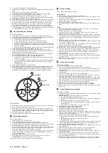
10. Install ring gear (228) and planetary assembly in reduction gear housing (241).
Time planetary gears with ring gear, as shown in Dwg. MHP3020 on page 9,
A
. Timing Mark;
B
. Ring Gear;
C
. Planet Gear. Using a separate ring gear tool to
maintain gear position during installation of planetary assembly is helpful.
2
2
2
2
0
0
0
0
1
1
1
1
Planet Gear
Ring Gear
Timing Mark
A
B
C
(Dwg. MHP3020)
11. Install keys (224) in ring gear (225) and install in reduction gear housing (241).
12. Install oil seal (220) in brake cover (219).
13. Install brake cover (219) on reduction gear housing (241) using Loctite® 586
between contact surfaces. Secure with capscrews (218). Apply Loctite® 243 to
capscrew threads. Refer to “TORQUE CHART” on page 12 for torque requirements.
14. Install plugs (222) and washers (223).
15. Carefully install pinion shaft (237) through brake cover (219).
n
Bottom Hook Assembly
Refer to Dwg. MHP2975.
1. Install rings (150) on sprocket (376).
2. Press a bearing (149) onto each end of sprocket (376).
3. Install sprocket assembly between hook block halves (380) and (381).
4. Assemble split ring (377) and thrust bearing (378) on hook (382) or clevis (385).
5. Install assembled pieces between hook block halves (380) and (381).
6. Ensure split ring and bearing are correctly located in recess of hook block halves
and do not restrict halves coming together. Pack cavity with grease. Tap hook
block halves together and install threaded rods (375).
7. Install nuts (115) and lockwashers (154) on threaded rods (375). Ensure all nuts
have an equal amount of engagement. Refer to “TORQUE CHART” on page 12
for torque requirements.
8. Install axle (374) in hook block half (380).
9. Install plate (263) with capscrews (133) and lockwashers (119). Refer to
“TORQUE CHART” on page 12 for torque requirements.
10. Check hook or clevis swivels freely in hook assembly (370).
n
Trolley Assembly
Refer to Dwgs. MHP2970 and MHP2978.
Trolley Wheels
1. Install seal ring (128) in trolley wheel (124) bore.
2. Press two bearings (130) into each wheel. The shoulders on the bearings inner
races must face each other.
3. Install spacer (129) followed by seal ring (128) on the outside of bearings. Install
retainer ring (125) to secure parts.
4. Press wheel assemblies onto side plate axles.
5. Secure trolley wheels on side plate axles with spacers (127) and retainer rings
(126).
Trolley
1. Ensure bushings (110) are installed in support (111) and trolley axle (107).
2. Install sleeves (109) on trolley axle (107).
3. Install supports (111) on trolley axles (107).
4. Install caps (113) on ends of trolley axle (107). Secure caps in place with
capscrews (114) and lockwashers (105).
5. Install spacers (112) on supports (111). Spacers must be equally distributed on
both sides. Ensure trolley wheel spacing is correctly adjusted. Follow the steps in
mounting the trolley in the ”INSTALLATION” section in Product Information
Manual.
6. Install side plates (101) and (104) on the same side.
7. Loosely install spacers (112), caps (123), lockwashers (105) and capscrews (106)
on the ends of supports (111).
8. Insert screw rods (116) through one side plate and loosely secure with one nut
(115) on the inside and one on the outside.
9. Install one nut (115) on the other end of each screw rod (116).
10. Repeat steps 6 and 7 for remaining side plates (102) and (103) on opposite side.
11. Install remaining nuts (115) on screw rods (116). Tighten nuts (115) and
capscrews (106). Refer to “TORQUE CHART” on page 12 for torque requirements.
12. If removed, install roller axles (122) and rollers (120) on side plates with
capscrews (121).
13. Mount trolley reduction gear assembly to side plates (102) and (103).
14. Secure trolley reduction gear assemblies to side plates using capscrews (270) and
lockwashers (271).
15. Install pinion (136), key (656), washer (135), lockwasher (119) and capscrew
(133) on planet support (655).
n
Trolley Motor Assembly
Refer to Dwg. MHP1651.
1. Press bearings (305) into motor flange (306).
2. Insert screw (301) through washer (302) and secure bearings.
3. Insert motor gears (312) and (313) into motor flange. Ensure drive gear (313) is
in lower position.
4. Immobilize the motor gears with a rod between the teeth. Install and tighten
locknuts (304).
5. Insert ‘O’ rings (307) into recess in motor flange (306).
6. Slide motor housing (308) over motor gears, with large slide valve port facing
away from motor flange. Press pins (309) into motor housing.
7. Insert slide valves (316) into valve ports followed by springs (317). Slide quad
rings (319) and (321) onto slide valve (318), lubricate and insert into valve ports.
8. Press bearings (314) onto motor gears and secure with retainer rings (315).
9. Insert ‘O’ rings (311) into recesses in motor housing (308).
10. Lubricate stops (322) and insert into recesses in motor cover (325).
11. Place motor cover over motor housing, align pins and press together.
12. Apply Loctite® 243 to screws (328) holding motor cover, insert through cover and
secure cover.
n
Trolley Reduction Gear Assembly
Refer to Dwg. MHP2978.
1. Install oil seal (652) and bearing (130) in flange (651). Lip of seal must be toward
planetary gear side.
2. Assemble planetary assembly if previously disassembled.
a. Install bearing (660) in planet gear (661).
b. Install a thrust bearing (659) and washer (658) on either side of planet gear
(661).
c. Install assembled planet gear in planet support (655).
d. Install planet pin (657) in planet support (655). Align pin hole with hole in
planet support.
e. Tap pin (662) into planet support to secure planet pin.
3. Install bearing (130) on planet support (655).
4. Install planet support (655) in flange (651).
5. Install bearings (665) and (405) in gear housing (668).
6. Install drive shaft (663) and retainer ring (664).
7. Install ring gear (654) and gear housing (668) on flange (651) and secure with
capscrews (650). Apply Loctite® 243 to capscrew threads. Refer to‘Torque Chart’
on page 12 for torque requirements.
8. Assemble planetary assembly if previously disassembled.
a. Install spacer (675) with a bearing (674) on either side into planet gear
(676).
b. Install assembled planet gear in planet carrier (673).
c. Install planet pin (677).
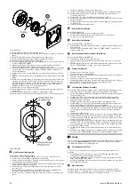
9. Install planet support assembly in ring gear (670). Position planet gears to obtain
correct timing. Refer to Dwg. MHP1560 on page 10,
A
. Timing mark just off
center line;
B
. Timing mark just off center line.
10. Install ring gear (670) assembly in gear housing (668). Verify timing position has
been maintained.
11. Install bearing (679) and retainer ring (683) on sun gear shaft (678).
12. Install ring gear (686), bearing (685) and planet support (673).
13. Install gasket (667) and brake housing (689) on gear housing (668). Check holes
are correctly aligned.
14. Lubricate and install ‘O’ rings (691) and (693) on piston (692). Clean excess
silicone from piston (692) and bore of brake housing (689). Area must be clean
prior to installing piston (692).
15. Install piston (692) in brake housing (689). Ensure ‘O’ ring in bore of piston is
located toward brake housing. Refer to Dwg. MHP1627 on page 10,
A
. ‘O’ Ring.
Form MHD56416 Edition 1
9


