MAINTENANCE
WARNING
• Never perform maintenance on the hoist while it is supporting a load.
• Before performing maintenance, tag controls:
WARNING - DO NOT OPERATE EQUIPMENT BEING REPAIRED.
• Only allow Ingersoll Rand trained technicians to perform maintenance.
• After performing any maintenance on the hoist dynamically test the hoist to
100% of its rated capacity, in accordance with ASME B30.16 standards,
before returning hoist to service. Testing to more than 100% of rated
capacity is required to set overload device and may be required to comply
with standards and regulations set forth in areas outside the USA.
• Shut off air system and depressurize air lines before performing any
maintenance.
• Use of other than genuine Ingersoll Rand replacement parts may result in
safety hazards, decreased performance and increased maintenance and may
invalidate all warranties.
n
Maintenance
Correct disassembly (to prevent loss or damage of good parts), repair, assembly,
testing and adjusting are critical to proper hoist operation. Maintenance procedures
are technical in nature and require training and experience to accomplish correctly.
In addition, repair and testing require specialized equipment that is not typically
found at the hoist-mounting site.
Proper use, inspections and maintenance increase the life and usefulness of your
Ingersoll Rand
equipment. During assembly, lubricate gears, nuts, capscrews and all
machined threads with applicable lubricants. Use of antiseize compound and/or
thread lubricant on capscrew and nut threaded areas prevents corrosion and allows
for easy disassembly of components.
It is extremely important that anyone involved with maintaining the hoist be familiar
with the servicing procedures of these products, and be physically capable of
conducting the procedures. These personnel shall have skills that include:
1. Proper and safe use and application of mechanics common hand tools as well as
special
Ingersoll Rand
or recommended tools.
2. Safety procedures, precautions and work habits established by accepted industry
standards.
Ingersoll Rand
cannot know of, or provide all the procedures by which product
operations or repairs may be conducted and the hazards and/or results of each
method. If operation or maintenance procedures not specifically recommended by the
manufacturer are conducted, it must be ensured that product safety is not endangered
by the actions taken. If unsure of an operation or maintenance procedure or step,
personnel should place the product in a safe condition and contact supervisors and/
or the factory for technical assistance.
n
Maintenance Intervals
Refer to Table 5 ‘Maintenance Interval Chart’ on page 3 for recommended maintenance
schedule.
n
Adjustments
n
Disc Brake
Disc brake adjustment is not required. If disc brake does not hold rated load,
disassemble and repair.
If brake slippage occurs during tests prior to placing hoist in service or during normal
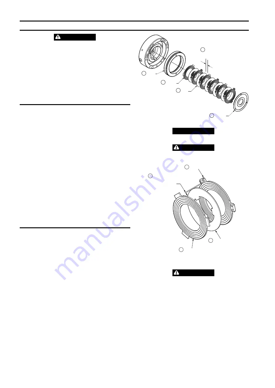
use of the hoist, follow the hoist disassembly procedure and check friction plates (66)
and (72) thickness as shown in Dwg. MHP2638 on page 6,
A.
Piston;
B.
Friction
Plate;
C.
Drive Plate;
D.
Reaction Plate;
E.
0.047 inch (1.2 mm) minimum. If this
dimension is less than shown, the friction plates (66) and (72) must be replaced.
Use the following procedure to remove the brake.
1. Remove the motor as described in ‘Motor and Disc Brake Removal’ on page 9.
2. Remove the reaction plate (68), friction plates (66) and (72), drive plates (67)
and piston (63).
3. Inspect the friction plates (66) and (72) for wear. If friction plate thickness is
uneven or is less than 0.047 in (1.2 mm) replace friction plate.
4. Remove, discard and replace ‘O‘ rings on piston (63).
No further disassembly is required, if only the brake is to be serviced.
Piston
Friction
Plate
Drive
Plate
0.047 inch minimum
(1.2 mm minimum)
A
B
C
Reaction
Plate
D
E
(Dwg. MHP2638)
NOTICE
• Original brake friction plate thickness is 0.059 in (1.5 mm).
WARNING
• Ensure drive plates make full contact with the friction plates, without
interference with spring clips.
Drive Plate
Friction Plate
A
B
C
D
Do not push spring clips
to the point of interference
with Drive Plate
Spring Clip
(Dwg. MHP3046)
n
Overload Device (optional feature on non EU hoists)
CAUTION
• Overload is factory set and should not be adjusted without consulting an
Ingersoll Rand trained technician.
6
Form MHD56279 Edition 4


