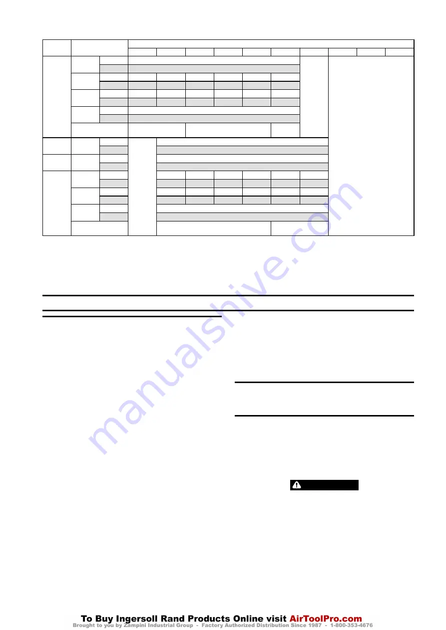
Table 8: Winch Bolt Hole Mounting Dimensions - Refer to Dwg. MHP0133 on page 11; A. Drum.
Models
Dimension
Drum Length (inches)
8
12
16
20
24
30
36
40
42
50
FA2.5i
(Note 1)
“A”
inch
20
Note 3
Note 3
mm
508
“B” *
inch
7
9
7.5
9
10
12
mm
178
229
190
229
254
305
“B” **
inch
6
8
7
8
9
11
mm
152
203
178
203
229
279
“C”
inch
0.6875
mm
17.5
Bolt Hole Qty each
Siderail
3
4
4
FA5i
“A”
inch
N/A
31.25
mm
794
FA2.5i-CE
“A”
inch
34.25
mm
870
FA5Ti/
FA5Ti-CE
(Note 2)
“B” *
inch
7.5
9
10
10.5
10
11
mm
190
229
254
267
254
279
“B” **
inch
6
6.25
8.5
9
12
14
mm
152
159
216
229
305
356
“C”
inch
0.8125
mm
20
Bolt Hole Qty each
Siderail
4
(4) 5
*
Drum with Manual or Automatic Drum Brake
**
Drum without Manual or Automatic Drum Brake
N/A
Not Available
Note 1:
30 and 36 inch Drum with Band Brake will require 5 bolts, without Band Brake 4 bolts.
Note 2:
20 inch Drum with Band Brake will require 5 bolts, without Band Brake 4 bolts.
36 inch Drum with Band Brake will require 6 bolts, without Band Brake 5 bolts.
Note 3:
Contact Factory
OPERATION
n
Winch Controls
The spring loaded, motor mounted, live air manual throttle control valve is supplied
as a standard feature on this winch. Optional remote throttle controls are available.
Reference model code on the winch data (name) plate and compare it to
“SPECIFICATIONS” on page 3, to determine your configuration. The throttle controls
provide operator control of motor speed and direction of drum rotation.
n
Winch Mounted Air Throttle
Refer to Dwg. MHP1809 on page 11, A. Haul-In; B. Exhaust Port; C. Lift Slider Handle
UP to Unlock; D. Payout; E. Air Inlet Port; F. Brake Release Port.
The winch control throttle valve is spring loaded, full flow air and mounts to the
motor rotary housing.
To operate control valve, place palm of hand on control knob and wrap fingers
around flange of sliding handle. Squeeze fingers, lifting sliding handle up to unlock
control handle. Shift control handle in desired direction to payout or haul-in wire
rope. As viewed from air motor end, move control throttle handle to the right
(clockwise) to payout wire rope and to the left (counterclockwise) to haul-in wire
rope. Avoid sudden movements of handle to ensure smooth operation of winch.
When released, handle will return to neutral or center position, sliding handle will
drop down to engage and lock control handle in place.
n
Remote Full Flow Air Throttle
Refer to Dwg. MHP2043 on page 13, A. To Brake; B. Threaded Ports.
Provides for remote mounting of winch control at a fixed location at up to 20 feet (6
metres) away from winch motor. Air hoses connect throttle to winch motor to
provide winch operation.
Move control throttle handle to the right (clockwise) to payout wire rope and to the
left (counterclockwise) to haul-in wire rope. Avoid sudden movements of control
valve to ensure smooth operation of winch.
n
Remote Pilot Pendant Throttle
Refer to Dwg. MHP2398 on page 13, A. Red - Air Supply; B. Green; C. Yellow; D.
Payout load; E. Haul-In Load.
Provides for remote winch control at distances of up to 66* feet (20 metres) away
from winch. The pilot pendant control throttle is a two function movable control
station for winch operation. Pilot pressure from pendant control activates winch
control valve. The winch control valve, located on winch motor, controls motor
speed and direction of drum rotation. Direction of drum rotation is determined by
the pendant lever/button depressed.
n
Remote Pilot Lever Throttle
Provides for remote winch control at distances of up to 66* feet (20 metres) away
from winch. The lever pilot control throttle is a fixed mounted lever control station
for winch operation. Pilot pressure from lever pilot control throttle activates winch
control valve. The winch control valve, located on winch motor, controls motor
speed and direction of drum rotation. Direction of drum rotation is determined by
the direction in which lever is shifted.
* For distances greater than 50 feet (15 metres) contact Ingersoll Rand Technical
Sales for control suitability.
n
Underwound Operation (optional feature)
Underwound operation allows wire rope haul-in or payout off the bottom of drum.
This is a special operation and requires a winch specifically designed for this usage.
n
Emergency Stop and Overload System
Emergency Stop and Overload System are standard on -CE winches.
Refer to Dwg. MHP2619 on page 11, A. Emergency Stop Button; B. Push Down to
Stop Winch Movement; C. Overload Valve Reset Button; D. Twist Red Button to Reset;
E. Overload Valve Adjustment Screw.
When emergency stop or overload valve is activated, winch drum rotation will
immediately cease.
CAUTION
•
If winch continues to move (payout load) after emergency stop activates,
brake(s) are not holding load and may require adjustment or repair.
When control valve senses a preset pressure difference between ports, a pilot signal
is sent to stop flow of air, winch drum rotation will immediately cease.
n
Emergency Stop
Emergency stop device is located on the control valve. When activated, winch drum
rotation will immediately cease. To activate emergency stop, depress (push down)
red palm valve, located on top of control valve.
Form MHD56434 Edition 6
7


