29
6.
Align the bore of bearing (247), washers (248) and link rod
(244).
7.
Apply Loctite
®
609 to the bore of bearing (247).
CAUTION
• Do not allow Loctite
®
609 to flow into the bearing, this can
cause part failure and motor damage. Ensure that washers
(248) are centered on the bearing. These are very thin and
can be sheared off, creating metal particles which can cause
component failure.
8.
Press pin (246) into bearing (247) until centered.
9.
Place ‘O’ ring (242) into groove on piston and lubricate.
10. Place piston sleeve (243) over ‘O’ ring (242).
Piston Mounting
Position motor housing onto adapter side of housing.
1.
Rotate crankshaft pin (213) until it is opposite the square
portion of the cylinder port in the motor housing.
2.
Insert a piston assembly through the motor cavity and out
the cylinder port (with the square portion). Lift the piston
rod up into this square area.
3.
Slowly rotate the crankshaft until the bearing (245) will
slide onto the crankshaft pin.
4.
Repeat steps 2 and 3 for the other piston assembly.
5.
Insert setscrew (218) into the top of counterweight (214)
and engage a couple of threads.
6.
Slide counterweight onto crankshaft pin.
CAUTION
• The flat side of the counterweight must face the piston rods
with the raised portion facing away. Failure to do this will
result in damage to components.
7.
Align the setscrew hole in the crankshaft pin (213) with
setscrew (218) and tighten.
8.
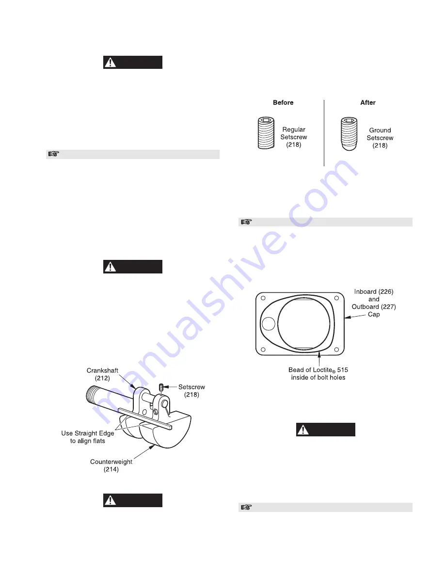
The flats on counterweight must align within 1/16 in (2
mm) of the flats on the crankshaft. Use a small metal flat
edge to check. Refer to Dwg. MHP1307.
Counterweight Alignment Check
(Dwg. MHP1307)
CAUTION
• Failure to properly align counterweight on crankshaft may
cause extreme motor vibration, resulting in damage to the
winch motor.
9.
If greater than a 1/16 in (2 mm) difference between the
counterweight and crankshaft flats then the end of the
setscrew should be ground. Grind very small amounts off of
setscrew. Refer to Dwg. MHP1276. Repeat process until
tolerance is met. If this tolerance is exceeded then the
crankshaft will be out of balance, resulting in extreme
motor vibration and possible damage.
Setscrew (218) Adjustment
(Dwg. MHP1276)
10. Tighten the socket head capscrew (216) to 185-195 in lb.
(68-72 Nm), while holding flatwasher (215) centered on
capscrew. Check tightness of setscrew (218).
Cylinder Assembly Installation
Position motor housing back on its side.
1.
Lubricate the inside of cylinders and pistons.
2.
Apply a 1/16 in (2 mm) bead of Loctite
®
515 around the
inboard cap (226) and outboard cap (227). Refer to Dwg.
MHP1297.
Cylinder Cap Sealant Placement
(Dwg. MHP1297)
3.
Place cylinder assembly over piston, push and twist into
position on motor housing.
CAUTION
• Ensure that the inboard and outboard cylinder assemblies
are in the correct position. This is noted by the offset position
of the air inlet holes.
4.
Coat capscrews (229) with anti-seize compound. Insert
capscrews through cap assemblies into motor housing and
tighten to 145-150 in lb. (54-56 Nm).
Motor Cover Installation
1.
Apply a 1/16 in (2 mm) bead of Loctite
®
515 around the
motor cover (223). Refer to Dwg. MHP1318.
Summary of Contents for FA2A
Page 8: ...7 ...
Page 38: ...37 WINCH CROSS SECTION DRAWING ...
Page 39: ...38 WINCH ASSEMBLY PARTS DRAWING ...
Page 41: ...40 MOTOR ASSEMBLY PARTS DRAWING ...
Page 47: ...46 CONTROL VALVE ASSEMBLY PARTS DRAWING ...
Page 49: ...48 REMOTE PENDANT AND CONTROL VALVE ASSEMBLY PARTS DRAWING ...
Page 53: ...52 EMERGENCY STOP AND OVERLOAD ASSEMBLY PARTS DRAWING ...
Page 55: ...54 REMOTE EMERGENCY STOP AND OVERLOAD ASSEMBLY PARTS DRAWING ...


