Ingersoll-Rand CENTAC Technical Reference Manual Download Page 21

CMC TECHNICAL REFERENCE MANUAL

1X36003 Version 2.52

 1996-1999 Ingersoll-Rand Company

Date of Issue: 18-Oct-1999

11

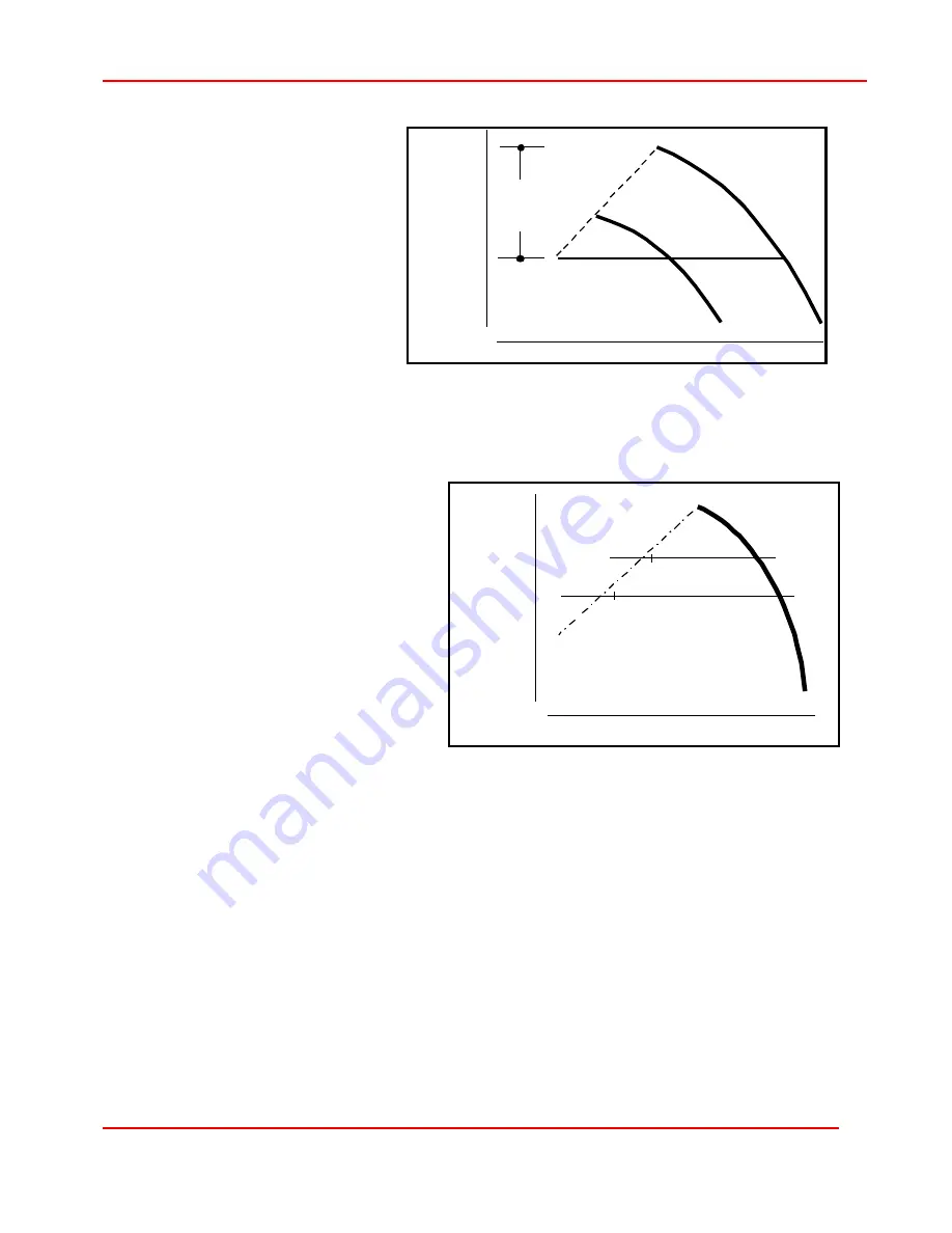
Typically sufficient rise to surge
exists when a ten- percent rise
to surge can be achieved for the
hottest ambients that are
expected for the site. If this
design criterion is followed, the
control system should be able
to prevent surge for variations in
air demand and inlet
temperature. The same design
methodology applies for
changes in cooling water
temperature for multi-stage
compressors.

Changes in System Discharge Pressure

MinLoad

 corresponds to a specific

constant discharge pressure;
therefore, if the discharge pressure
changes, 

MinLoad

 must be reset to

properly control surge. As shown in
Figure 9, when the discharge
pressure is changed from point 1 to
2, a surge can occur at point 2 if

MinLoad

 is not reset.

Changes in system discharge
pressure also apply, but more subtly,
when the compressor begins to age.
Dirty inlet filter elements and fouled
coolers can change the
compressor's natural curve; so

MinLoad

 should be checked

periodically to prevent surge from an
incorrect setting.

Rapid System Demand Changes

When the system demand varies rapidly over a wide range of capacity, the controller may
not react fast enough to open the bypass valve to prevent surge. The CMC reads discharge
pressure, motor amps, and approximately twenty other pressure and temperature inputs;
plus controls the inlet and bypass valve position. The time required to do all of this
approximately 100 milliseconds. When the controller is too slow to react, it is referred to as
"driving through 

MinLoad

". The only prevention for a situation like this is to set 

MinLoad

 at a

more conservative value. The only negative implication to this is reduced energy savings,
because the bypass valve is opened early.

Incorrect Instrumentation Output

If the instrumentation, defined in Figure 4, is improperly calibrated or gives inaccurate
readings, the compressor could surge even though the CMC thinks it should not. Areas of

Capacity

Discharge

Pressure

Rise

To

Surge

T=cold

T=hot

Figure 8: Rise To Surge

Capacity - Mass Flow

Discharge

Pressure

TL

1

TL

2

Figure 9: Changes in Discharge Pressure

Summary of Contents for CENTAC

Page 1: ...CENTAC CMC Technical Reference Manual INGERSOLL RAND AIR COMPRESSORS...

Page 2: ...AL IS SOLD AS IS AND WITHOUT ANY EXPRESSED OR IMPLIED WARRANTIES WHATSOEVER Printing Date 18 October 1999 Ingersoll Rand air compressors are not designed intended or approved for breathing air applica...

Page 3: ...___________________________________ 11 Incorrect Instrumentation Output _____________________________________________________ 12 How is Surge Detected _________________________________________________...

Page 4: ...GS Folder ___________________________________________________________________ 29 General Sequence of Operation _____________________________________________34 Indicator Switch and Light Layout _______...

Page 5: ..._________ 63 Digital Input System DIS _____________________________________________________________ 64 Checking proper operation of the digital devices _______________________________________ 65 Contr...

Page 6: ...________76 Performance Control _________________________________________________________________ 76 Motor Current MinLoad and MaxLoad_________________________________________________ 76 Surge Control_...

Page 7: ..._______________ 98 Example Presetting a Single Register 16 bit Integer _________________________________ 99 Function 15 0F Hex Force Multiple Coils ____________________________________________ 99 Exam...

Page 8: ...ommand 0F Function AA SLC Typed Logical Write___________________________________ 127 Example Presetting Analog Setpoint for 32 bit Value_________________________________ 127 Example Presetting a 16 bi...

Page 9: ..._______________________________________ 145 Setting UCM Switches ______________________________________________________________ 145 UCM Port Activity LEDs _____________________________________________...

Page 10: ...ontrol 5 Figure 3 Modulate Control 5 Figure 4 Performance Control 6 Figure 5 Proportional Band Pb 7 Figure 6 Proportional Plus Integral Control 8 Figure 7 MinLoad and MaxLoad 8 Figure 8 Rise To Surge...

Page 11: ...urge turbine operation multiple board failure and control parameter edits from both local or remote control locations This added information is invaluable for troubleshooting 6 Allen Bradley DF1 commu...

Page 12: ...ciples and Design John Wiley Sons 1985 Rowland James R Linear Control Systems Modeling Analysis and Design John Wiley Sons 1986 Deshpande Pradeep B and Ash Raymond H Computer Process Control With Adva...

Page 13: ...lected for accurately controlling and protecting Centac and X FLO compressors Features of the CMC system are Ease of use only twelve buttons to push on the operator OUI Multiple function 240 x 128 pix...

Page 14: ...mpressor is being vented to the atmosphere In this mode the inlet valve is slightly open to allow enough air to pass through the compressor for internal cooling prevention of rotor instability and sur...

Page 15: ...ulate is the most commonly used control method for Centac and X FLO compressors EnergySavingControl Autodual Autodual automatically loads the machine when demand is high and unloads the machine when d...

Page 16: ...usage requirements the CMC could be preprogrammed to respond to those changes however all plant air systems are not alike The frequency and variability of the capacity changes means that the control...

Page 17: ...onse when the difference between actual and set point pressures is zero There is no response Proportional control only functions when a difference or error exists Design discharge pressure could not b...

Page 18: ...be re evaluated any time there is a major change in the compressed air system Up to this point constant pressure control has been accomplished with an analog input system pressure and two analog outp...

Page 19: ...7 cannot be attained for the T hot curve because it is beyond the maximum compressor capability that is the inlet valve is fully open This scenario never limits the inlet valve When ambient conditions...

Page 20: ...is required ControlMethodology Surge prevention is accomplished by opening the bypass valve prior to reaching the surge point The point at which the bypass valve opens is MinLoad By blowing a portion...

Page 21: ...ange the compressor s natural curve so MinLoad should be checked periodically to prevent surge from an incorrect setting Rapid System Demand Changes When the system demand varies rapidly over a wide r...

Page 22: ...it has been shown that even though the CMC has surge prevention logic a surge can still occur The CMC has a surge detection system comprised of a surge pressure transducer and motor current transform...

Page 23: ...can happen When MinLoad is set too high the compressor will consume excessive power at MinLoad When MinLoad is set too low the compressor is allowed to go past the surge line and surge occurs When Sur...

Page 24: ...the compressor start button is pushed and the programmable timer Start Time has expired The pump does not come on again until the Stop key is pressed and will remain on until the panel power is turne...

Page 25: ...d transmitters to measure temperature eddy current based vibration transmitters to measure shaft vibration and a current transformer to measure the motor current The CMC logic used for the protective...

Page 26: ...sixteen digital outputs are used by the CMC to start the prelube pump energize the main starter contacts indicate that an alarm or trip condition exists indicate that the compressor is unloaded activa...

Page 27: ...timer is set at the factory for two minutes 120 seconds and is not adjustable This period allows the compressor prelube pump to circulate oil throughout the casing and prevents restarting while the c...

Page 28: ...just reasons for being in the Unloaded state A D Unloaded means AutoDual Unloaded which occurs when AutoDual is enabled and the system pressure has been high enough for a long enough time to drive an...

Page 29: ...e states relative to valve position This diagrams is provided to assist in the understanding of overall compressor operation Unloaded Coasting Starting Loading Loaded MinLoad Full Load Loaded MaxLoad...

Page 30: ...e OUI and four buttons lights and switches on the device plate The CMC OUI consists of six command buttons Start Stop Load Unload Acknowledge and Reset four navigation keys Up Right Left and Down an E...

Page 31: ...en the SETTINGS folder is displayed and the RIGHT key is pressed the SYSTEM folder becomes active PAGE NAVIGATION To move among each folder s pages press the UP and DOWN keys The page list is also cir...

Page 32: ...es various types of information about the unit and the SETTINGS folder is used to perform compressor setup Status Bar The Status Bar provides four distinct types of information Compressor Operating St...

Page 33: ...a more thorough determination is required the operator can get additional detail by looking through the other pages in the system The Page Number indicates the current page for the current folder with...

Page 34: ...xLoad HLL 400 0 User Setpoint TL 100 0 Surge Index Increment 1 0 Control Setpoint 100 0 Surge Absorber Enabled Surge Sensitivity 9 0 MinLoad 6 6 SYSTEM SETTINGS INFO Loaded Remote Load Selected Alarm...

Page 35: ...rent is in Amps and valve positions are in percent open Pressure Setpoint is always editable while the Inlet and Bypass Valve positions are edit enabled when in the Manual mode only These are the only...

Page 36: ...our pages give the current operating status for the compressor The User is always within two keystrokes of all operating parameters INFOFolder The INFO folder contains the OUI key map the compressor e...

Page 37: ...PID Pb The Bypass Valve Pressure PID Proportional Band value has been edited from location x Edit x Coasting Timer The Coasting Timer value has been edited from location x Edit x CT Ratio The CT Rati...

Page 38: ...on Starter Failure Starter feedback was not received after a Start command was issued Stop Location A Stop command has been issued from Location Surge The controller has detected a Surge Surge Unload...

Page 39: ...ints except Pressure Setpoint Throttle Limit language selection and the Password these items are always modifiable Each control system is shipped with two languages and units of measure combinations T...

Page 40: ...surge has been detected If the value for Surge Index Increment is equal to zero Surge Indexing is disabled To reset the MinLoad Control Setpoint to the MinLoad User Setpoint hold the reset key for at...

Page 41: ...et the MinLoad Control Setpoint to prevent excessive air bypass CAUTION Repeated surging can cause damage to the compressor therefore use caution when desensitizing the Surge Sensitivity setting The C...

Page 42: ...tton selector To change the selection press the Up or Down arrow key Reload Percent Unload Point and Unload Delay Time are all setpoints for Autodual control Checking the Manual checkbox enables manua...

Page 43: ...e Trip Enable tests that the zero amp motor current has been reached after a start command has been initiated and that motor current is not lost while the compressor is running Uncheck this box for dr...

Page 44: ...t 2 Look for Ready To start and load a compressor follow steps 1 2 3 and 4 Press Stop Press Unload wait 20 seconds 5 6 To unload and stop a compressor follow steps 5 and 6 Press Start 3 4 Press Load U...

Page 45: ...ght PushButtons The red EMERGENCY STOP push button stops the compressor any time that it is pressed This push button is used to initiate a stop in the case of an emergency Switches The CONTROL POWER O...

Page 46: ...eventually hit the surge line and surge By stopping inlet valve throttling at MinLoad the machine is kept out of surge To find the MinLoad setting the machine is run into the surge line and the value...

Page 47: ...by unchecking the manual check box Setting MinLoad Surge Index Increment When Surge Indexing is enabled MinLoad Surge Index Increment is greater than zero the Index Increment value is the amount added...

Page 48: ...orded if the message is not displayed surge was not recorded 8 Check the Surge Sensitivity setting a If the surge was recorded the setting may be correct or the Surge Sensor may be too sensitive skip...

Page 49: ...trol loop For each PID loop Proportional Integral and Derivative parameters are used to stabilize the system For a definition of the parameters and their effect on stability refer to the section title...

Page 50: ...ve requiring positioning 7 Use the vertical arrows to increment and decrement the valve position sent to the valve NOTE For the Inlet and Bypass Valves the displayed position corresponds to percent op...

Page 51: ...rough the Unload Point Typically when the check valve closes system demand requires the check valve to open again soon thereafter due to the demand being on the verge of requiring the compressor If th...

Page 52: ...ivide the primary by the secondary and enter the value as the CT Ratio Example CT is printed with 600 5 the value entered is 120 Inlet Unload Position The purpose of this variable is to set the inlet...

Page 53: ...age in the OUI Status Bar 2 Determine overshoot a Load the machine b Monitor the pressure overshoot 3 If overshoot is excessive a Decrease the Setpoint Ramp Rate b Repeat step 2 4 If overshoot is sati...

Page 54: ...o specific items which can cause a particular fault I O FAULT Temperature pressure load valve etc readings incorrect Refer to the Input Output I O System COMPRESSOR RELATED Event correctly indicates a...

Page 55: ...ual oil pressure is low i The prelube pump is found to be running and installation of a calibrated pressure sensor shows the actual oil pressure to be above the Oil Pressure Trip Value Therefore the m...

Page 56: ...e 4 20 mA output Probe Gap setting 0 030 to 0 060 in 0 762 to 1 524 mm 0 050 in 1 27 mm is nominal gap Probe gap corresponds to 3 to 6 volts VDC 5 VDC nominal Probe ohm value 7 12 ohms Troubleshooting...

Page 57: ...X 100 4 20 mA PROBE INGERSOLL RAND To BCM J1 Connector See electrical schematic for point Checking Vibration Circuit VMS 2 1 With control power on check the dc voltage at the COM and TEST terminals on...

Page 58: ...VDC mA VAC mA COM V XXXXX XXXXX XXXXX XXXXX XXXXX XXXXX Probe extension cable Vibration probe Compressor casing Connect test lead to inner pin Connect test lead to outer shell Probe connector Checking...

Page 59: ...ary the signal If the value tracks according to the table below the wiring is faulty 3 Verify the connector at J1 is fully seated If the value does not track correctly the BCM may be faulty J2 Floatin...

Page 60: ...g or in the control panel enclosure The transmitter is supplied 24 VDC and outputs 4 20mA over a fixed range of either 0 to 200 F 17 7 to 93 3 C or 0 500 F 17 7 to 260 C Troubleshooting The following...

Page 61: ...ransmitter and connect a voltmeter to these wires 2 With control power on there should be approximately 24 VDC present at the terminals 3 If approximately 24 VDC is not present see the section titled...

Page 62: ...a Faulty RTD TMS 2 1 Turn control power off 2 Check ohms versus temperature Use an Ohmmeter and the following tables to determine if the RTD is faulty Vary the temperature to the RTD and check the oh...

Page 63: ...142 30 142 50 142 70 142 90 143 10 143 30 143 50 143 80 144 00 144 20 240 144 40 144 60 144 80 145 00 145 20 145 40 145 60 145 90 146 10 146 30 250 146 50 146 70 146 90 147 10 147 30 147 50 147 70 147...

Page 64: ...143 34 143 55 143 76 143 97 144 18 115 56 144 39 144 59 144 80 145 01 145 22 145 43 145 64 145 85 146 06 146 27 121 11 146 48 146 69 146 90 147 11 147 32 147 53 147 73 147 94 148 15 148 36 126 67 148...

Page 65: ...power off connect a 100 ohm resistor to terminals 3 and 4 of the transmitter 2 Turn control power on the OUI reading should be 32 F 0 C 10 3 If the reading is not within specification the transmitter...

Page 66: ...as the simulator output is varied 3 If the reading on the OUI is incorrect or does not change turn control power off and reconnect the 4 to 20 mA simulator at the respective terminals at connector J1...

Page 67: ...version to a pneumatic signal for positioning the inlet or bypass control valve Specification 4 20mA input 3 to 15 psi output 60 to 120 PSIG instrument air input to I P Troubleshooting The following t...

Page 68: ...rical schematic 2 Restore control power 3 If the meter reads 4 mA the BCM is satisfactory 4 If 4 mA is not present refer to the section titled Control Power System 5 Restore connections 6 Remove contr...

Page 69: ...the supply connection on the I P 3 Vary the simulator between 4 20 mA The output of the I P and the positioner should follow If the valve tracks the 4 20 mA signal correctly the I P and the positione...

Page 70: ...50 PSIG 344 75 kPa range 0 200 PSIG 1379 kPa range Power 24 VDC Troubleshooting The following table identifies typical problems probable causes and appropriate procedures for verifying the probable ca...

Page 71: ...s at the suspect PT and connect a voltmeter to these wires 2 With control power on there should be approximately 24 VDC present at the terminals 3 If approximately 24 VDC is not present see the sectio...

Page 72: ...If the reading on the OUI is incorrect or does not change turn control power off and reconnect the 4 20 mA simulator at the respective terminals at connector J1 see electrical schematic for connection...

Page 73: ...s coming from the PT 2 If there is no continuity either the wiring or the PT is faulty SPAN INGERSOLL RAND VDC mA VAC mA COM V XXXXX XXXXX XXXXX XXXXX XXXXX XXXXX M Functional PT test PMS 4 1 Remove c...

Page 74: ...d type 1 Low seal air pressure Pressure 2 Low cooling water flow Flapper 3 Low oil level Float 4 High condensate level Float 5 Dirty inlet filter Differential pressure 6 Dirty oil filter Differential...

Page 75: ...C selected between J4 or J5 pin1 and the input pin the input pin can be determined from the electrical schematic or wire number 3 Ensure the digital device is not in the trip condition the meter shoul...

Page 76: ...ribution are performed as shown below F100 F101 F102 F103 All BCM Fuses are 5x20mm GMA 1 5 amp Fast Blow Fuse 5A 250VAC normal blo Power Supply BCM J2 24 VDC pins 11 thru 14 Return pins 7 thru 10 J1 A...

Page 77: ...NGERSOLL RAND Centrifugal Compressor Division No CPU power CPS 8 BCM problems CMCS 3 OUI is black No AC power CPS 1 No DC power CPS 2 No OUI power CPS 7 Event Log indicates all digital alarms and trip...

Page 78: ...output power CPS 4 1 Ensure control power is off 2 Install a multimeter set for VAC between pin 1 at connector J12 on the BCM and the ground bar 3 Restore control power the meter should read 120 VAC o...

Page 79: ...mpany Date of Issue 18 Oct 1999 69 No CPU power CPS 8 1 Ensure control power is off 2 Verify approximately 24 VDC is present at J10 3 Check F100 if F100 is blown the BCM must be replaced not the fuse...

Page 80: ...ely a hardware or software problem which will require Ingersoll Rand support to correct Component Specification VDC power required Software required Troubleshooting The following table identifies typi...

Page 81: ...Replacement Procedure If the backlight does not fix the problem the OUI may be faulty OUI is black CMCS 2 1 Check for OUI power as described in the section titled The Control Power System If approxima...

Page 82: ...ow the maximum operating temperature allowed This action effectively extends the operating life of the control components A filter and gasket are added to attain a NEMA 12 rating NEMA4 IP65 This optio...

Page 83: ...gulate the amount of gas entering the panel A differential pressure switch is wired to a light on the front of the panel to indicate if there is a loss of purge gas A relief valve is installed to prev...

Page 84: ...push button is located on the CMC faceplate to silence any audible devices connected to the CMC board Running Unloaded Shutdown Timer The intent of this option is to save energy by shutting the compre...

Page 85: ...sure of at least 120 milliseconds For the start to proceed the panel power must be on the compressor must be in the Ready state all utilities must be running and permissive functions satisfied and the...

Page 86: ...as there are no analog input error faults for this channel and the change made will rounded to the nearest step value 0 1 size This methodology prevents the control system from chasing an ever changi...

Page 87: ...essed to get enough steam to the turbine to get the speed above the Zero Offset Speed This speed is defaulted to 15 rpm If this speed is not achieved in this time period the event message Accelerate 1...

Page 88: ...pressors and it means that the turbine trip and throttle valve limit switch has not been made System Folder Replacing Motor Current with Compressor Speed on Page 1 is the only modification to this fol...

Page 89: ...Load Protection 1 MaxLoad HLL amps is replaced with MaxLoad HLL rpm 2 User Setpoint TL amps is replaced with User Setpoint TL IV Pos 3 Control Setpoint amps is replaced with Control Setpoint IV Pos 4...

Page 90: ...Idle in the CMC and is sent on the discrete output Driver Speed Rated Idle to the governor 3 When the two minute waiting timer has expired the compressor is NOT READY Unloaded Coasting Starting Loadi...

Page 91: ...ed This signal is sent to a discrete input Trip and Throttle Valve Limit Switch on the CMC 9 When the limit switch is energized and no stop command is pending the compressor will be READY This state m...

Page 92: ...ned to the Rated position 13 When the turbine speed exceeds Maximum Slow Roll Speed the Starting Timer begins 60 seconds maximum and is STARTING This is the same time for motor driven compressors ther...

Page 93: ...pressors have similar characteristics as the turbine driven compressors The differences are 1 Idle Rated Driver Speed discrete input and discrete output are eliminated 2 Start Momentary Stop Momentary...

Page 94: ...en see CEM Instruction Manual for details A user might want to log specific data rather than all data The options are endless Adding each of these features requires reprogramming and testing custom pr...

Page 95: ...tions The CMC MODBUS Interface defines the message structure that a CMC uses to exist on a MODBUS network This interface will allow the MODBUS network to gather information and control the compressor...

Page 96: ...ntain the data type and a four digit number are referred to as absolute e g address 30232 where 3 is the data type for a input register and 0232 or 232 is the address Software products at the operator...

Page 97: ...bit two bytes one word chunks For each two byte word the left most byte is the most significant For each byte the left most bit is the most significant This portion of the message changes with each f...

Page 98: ...8 00207 00 CE Compressor State Ready 00192 00 BF Digital Output Channel 6 J14 P5 6 00208 00 CF Compressor State Surge Unload 00193 00 C0 Digital Output Channel 7 J14 P3 4 00209 00 D0 Compressor State...

Page 99: ...6 9 the hexadecimal data byte 10 0001 0000 binary means that Channels 16 15 14 12 11 10 and 9 are off and Channel 13 prelube pump is running is on The following table graphically depicts this example...

Page 100: ...e Address hex Input Name Read Only 10171 00 AA Digital Input Channel 1 J4 P2 10172 00 AB Digital Input Channel 2 J4 P3 10173 00 AC Digital Input Channel 3 J4 P4 10174 00 AD Digital Input Channel 4 J4...

Page 101: ...t Registers NOTE Since MODBUS is a 16 bit system the programmer must get two 16 bit numbers and combine them into one 32 bit floating point number The first method uses two 16 bit integers to represen...

Page 102: ...0093 00 5C 40094 00 5D 43093 0C 14 Analog Input Channel 5 J1 P5 High Alarm Setpoint 40095 00 5E 40096 00 5F 43095 0C 16 Analog Input Channel 5 J1 P5 Low Alarm Setpoint 40097 00 60 40098 00 61 43097 0C...

Page 103: ...0 96 40152 00 97 43151 0C 4E Analog Input Channel 12 J1 P20 Low Alarm Setpoint 40153 00 98 40154 00 99 43153 0C 50 Analog Input Channel 12 J1 P20 Low Trip Setpoint 40155 00 9A 40156 00 9B 43155 0C 52...

Page 104: ...point 40203 00 CA 40204 00 CB 43203 0C 82 Analog Input Channel 19 J1 P33 High Trip Setpoint 40205 00 CC 40206 00 CD 43205 0C 84 Analog Input Channel 19 J1 P33 High Alarm Setpoint 40207 00 CE 40208 00...

Page 105: ...tion 40283 01 1A 40284 01 1B 43283 0C D2 Start Timer 40285 01 1C 40286 01 1D 43285 0C D4 CT Ratio 40287 01 1E 40288 01 1F 43287 0C D6 Power On Hours 40297 01 28 40298 01 29 43297 0C E0 Running Hours 4...

Page 106: ...01 4B 43331 0D 02 Bypass Valve Pressure Integral Constant 40333 01 4C 40334 01 4D 43333 0D 04 Bypass Valve Pressure Derivative Constant 40335 01 4E 40336 01 4F 43335 0D 06 Compressor Control Mode 1 M...

Page 107: ...log Input Channel 8 J1 P12 30017 00 10 30018 00 11 33017 0B C8 Analog Input Channel 9 J1 P13 30019 00 12 30020 00 13 33019 0B CA Analog Input Channel 10 J1 P16 30021 00 14 30022 00 15 33021 0B CC Anal...

Page 108: ...2 Bit floating point number you must issue the following command The response from this command is So the System Pressure expressed as a floating point number is 110 4155731201 psi IEEE floating point...

Page 109: ...01 NOTE When Sign Exponent Mantissa 0 Value 0 This is a special case for the above equation Example Read Multiple Channels The procedure for reading multiple channels is the same as reading a single c...

Page 110: ...y should be sent once momentary and the CMC will execute the commands To remotely reset the compressor the following command is issued The response from this command is identical to the command sent F...

Page 111: ...NS DISABLED ENABLED selector switch is NOT considered when forcing coils or writing registers to the CMC Reads and Writes are always enabled Repeatedly writing a value to a register or forcing a coil...

Page 112: ...ce a reset absolute address 00222 relative address DD and start absolute address 00225 relative address E0 of the compressor the following command is sent The number of contiguous coils is four 00225...

Page 113: ...es for the number you want to send The process required is 1 Determine the sign positive 0 or negative 1 This is the first bit 2 Divide the decimal value by 2 until the result is less than 2 but great...

Page 114: ...ta bytes and the data bytes themselves are not echoed NOTE Sending 32 bit values are typically not necessary Sending the data as a 16 bit integer only or a 16 bit integer and 16 bit fraction will sati...

Page 115: ...when a master device sends a query to a slave device it expects a normal response in all other cases a time out or exception response is returned The four possible responses to a the master s query a...

Page 116: ...es the function code value in an exception response exactly 80 hexadecimal higher than the value would be for a normal response With the function code s most significant bit set the application progra...

Page 117: ...qual to zero 2 request for more than the maximum number of parameters 3 the force single coil command Function 05 is issued and the value is other than FF00 or 0000 4 the force multiple coil command F...

Page 118: ...e high 16 bits of the IEEE value for 100 5 Address 33008 contains the low 16 bits of IEEE value for 100 5 Additionally the type of data in a location determines the commands that can be used to access...

Page 119: ...CMC Microcontroller can communicate with other devices over a variety of communication standards Supported standards or protocols include RS 232 IRBUS Ingersoll Rand Proprietary Modicon s MODBUS and...

Page 120: ...d in the command data field vary from command to command NOTE The standard definitions of the control characters used by DF1 full duplex protocol are listed below Abbreviation Hexadecimal Value STX 02...

Page 121: ...The UCM DF1 driver uses mainly the higher nibble to report errors occur in CMC A special error code with non zero local error nibble 3Fh is used to report errors caused by illegal CMC data table addr...

Page 122: ...ed to calculate the CRC value The following explains how to calculate the CRC value Before starting the calculation a 16 bit register used to store the CRC value is cleared to be zero As a byte is fet...

Page 123: ...oating point number with respect to the received DF1 command The Allen Bradley PLC floating point format is a subset of IEEE STD 754 1985 Accessing data from the CMC via DF1 interface emulates accessi...

Page 124: ...Two Bytes Address decimal 15 14 13 12 11 10 9 8 7 6 5 4 3 2 1 0 B10 10 160 175 175 174 173 172 171 170 169 168 167 166 165 164 163 162 161 160 B10 11 176 191 191 190 189 188 187 186 185 184 183 182 18...

Page 125: ...tpoint 16 10 Analog Input Ch 16 J1 P28 57 39 Analog Input Ch 7 J1 P9 Lo Trip Setpoint 17 11 Analog Input Ch 17 J1 P29 58 3A Analog Input Ch 8 J1 P12 Hi Trip Setpoint 18 12 Analog Input Ch 18 J1 P32 59...

Page 126: ...MC TECHNICAL REFERENCE MANUAL 1X36003 Version 2 52 1996 1999 Ingersoll Rand Company Date of Issue 18 Oct 1999 41 29 Analog Input Ch 3 J1 P1 Lo Trip Setpoint 82 52 Analog Input Ch 14 J1 P24 Hi Trip Set...

Page 127: ...Valve Integral Constant 105 69 Analog Input Ch 19 J1 P33 Lo Trip Setpoint 164 A4 Reserved 106 6A Analog Input Ch 20 J1 P36 Hi Trip Setpoint 165 A5 Bypass Valve Proportional Constant 107 6B Analog Inpu...

Page 128: ...14 P1 2 135 87 MinLoad Throttle Limit TL 194 C2 Digital Output Ch 9 J13 P7 8 136 88 MaxLoad High Load Limit HLL 195 C3 Digital Output Ch 10 J13 P5 6 137 89 Autodual Reload Percent 196 C4 Digital Outpu...

Page 129: ...rted by the CMC Microcontroller Command 0F Function 68 PLC5 Typed Read The CMC is treated as a PLC5 when this command is issued This command reads a block of data from CMC starting at a specified data...

Page 130: ...s a floating point number is 100 2396 PSIG The following table contains a list of data types and the ID value of each supported by Allen Bradley DF1 protocol Data Type ID Data Type 1 bit 2 bit string...

Page 131: ...g Point Number If the UCM is configured to read data as floating point the following command is sent DLE STX DST SRC CMD STS TNS FN C Packet Offset Total Trans PLC5 System Address Size DLE ETX BCC 10...

Page 132: ...2 exponent 127 Mantissa 2 23 1 Value 10 2 133 127 6083782 2 23 1 110 4155731201 NOTE When Sign Exponent Mantissa 0 Value 0 This is a special case for the above equation Example Read Multiple Analog Ch...

Page 133: ...00 41 17 99 09 19 42 00 00 00 00 00 00 00 00 01 00 00 00 B DLE ETX BCC 00 00 00 00 00 00 00 00 00 00 00 00 10 03 3D Example Reading Bit Packed Discrete Data Reading discrete values from file number 10...

Page 134: ...or 32 bit Values To write 105 4 PSIG as a floating point number to the user pressure setpoint CMC data table address 86h issue the following command DLE STX DST SRC CMD STS TNS FN C Packet Offset Tota...

Page 135: ...rmine the exponent bits by It took us six iterations to get the result to a number that is less than two and greater than or equal to one Now we must add 127 for an exponent of 133 Converting this to...

Page 136: ...Total Trans PLC5 System Address 10 02 0D 11 0F 00 41 D0 67 00 00 02 00 07 00 0B 86 A B DLE ETX BCC 99 09 05 42 69 00 A0 0F 10 03 C0 The response from this command is DLE STX DST SRC CMD STS TNS DLE E...

Page 137: ...1999 Ingersoll Rand Company Date of Issue 18 Oct 1999 127 This function will override the CMC s current state The forced state will remain valid until the CMC next solves the coil The coil will remain...

Page 138: ...ETX BCC 10 02 11 0D 4F 00 E1 F8 10 03 BA The following command works the same DLE STX DST SRC CMD STS TNS FN C Packet Offset Total Trans PLC5 System Address 10 02 0D 11 0F 00 41 E3 67 00 00 02 00 07 0...

Page 139: ...point number the following command is issued DLE STX DST SRC CMD STS TNS FNC Byte Size File No File Type Ele No S Ele No DLE ETX BCC 10 02 0D 0B 0F 00 D4 19 A2 04 0B 8A 86 00 10 03 2B The response fro...

Page 140: ...r compressor you determine that the digital input for emergency stop push button is located on J4 P5 Channel 4 The CMC data table address is ADh for the input in question Therefore to read the state o...

Page 141: ...1 70 10 03 48 Example Presetting a 16 bit Integer and 16 bit Fraction Analog Setpoint To change the integer and fraction value for the user pressure setpoint to 105 4 PSIG issue the command below The...

Page 142: ...rted by the UCM DF1 interface To force a reset CMC data table address DDh and start E0h of the compressor the following command is sent DLE STX DST SRC CMD STS TNS FNC Byte Size File No File Type Ele...

Page 143: ...port EXT STS According to Allen Bradley DF1 protocol convention EXT STS is part of the message only if STS F0h N7 0 U 15 U 15 N7 0 First Pass S2 1 15 0000 EN DN ER MSG Read Write Message Type Read Wri...

Page 144: ...ves DLE ENQ or DLE NAK message it resends the last response to the command initiator When DLE ACK message is received by the UCM no response is returned When the UCM receives a command without any com...

Page 145: ...ervice Tool RS 232 to RS 422 RS 485 Converter Universal Comm Module UCM Universal Comm Module UCM IRBUS Address 2 Base Control Module BCM IRBUS Address 1 RS 232 Cable CENTAC Microcontrol ler CMC Panel...

Page 146: ...nk section SW 8 RS 232C RS 422A selection CAUTION The 1770 KF2 module reads the status of these communication option switches only at power up so you need to change switch settings with 1770 KF2 power...

Page 147: ...rk Link Communication Rate Switch assembly SW 5 lets you select the communication rate for the 1770 KF2 module s network link DH Set both switches ON for a network communication rate of 57 600 bits pe...

Page 148: ...M only supports DH network SW 7 should always select DH Network SW 7 Setting Mode 1 2 DH OFF OFF DH ON OFF SW 8 RS 232C RS 422A Selection The UCM DF1 interface uses RS 422 communication SW 8 should se...

Page 149: ...CMC TECHNICAL REFERENCE MANUAL 1X36003 Version 2 52 1996 1999 Ingersoll Rand Company Date of Issue 18 Oct 1999 139...

Page 150: ...reprogrammed 03h Commanded To Boot The BCM is currently in the process of being programmed If this message does not disappear after programming is completed power cycle the unit 04h Invalid Applicati...

Page 151: ...ny Date of Issue 18 Oct 1999 141 reoccurs 10h Low Power Power supply voltage 24 VDC dropped below minimum operating level Check power supply Cycle power when voltage is within proper operating limits...

Page 152: ...laced Cycling the power on the module will restart the system Once restarted the program will operate properly until the same condition reoccurs 13h Intermodule Data Error An error has occurred while...

Page 153: ...screte Inputs 24 VDC Channels 9 16 J6 RS232 Serial Data Link Display Female DB9 J7 RS485 Serial Data Link IRBUS Pin 1 J8 Speed Sensor Input 1 150 Hz J9 Current Transformer Input 0 5 Amps J12 Digital O...

Page 154: ...re Female 9 Position D Sub Miniature Male J7 RS485 IRBUS Serial Data Link na Phoenix MSTBA 2 5 6 G 5 08 Phoenix MSTB 2 5 5 ST 5 08 J8 Speed Sensor Input Variable Reluctance Phoenix MSTBA 2 5 3 G 5 08...

Page 155: ...g Input Channel 15 26 Power 24 VDC Channels 15 16 Pin J5 Digital Inputs Pin J13 Digital Outputs 27 Shield Channels 15 16 1 Power 24 VDC Channels 9 16 1 Digital Output Channel 12 28 Analog Input Channe...

Page 156: ...wer Phoenix MSTBA2 5 2 G 5 08 Phoenix MSTW2 5 2 ST 5 08 NOTES 1 OUI Weight 410 g 0 90 lb 2 OUI Size Length 267 mm 10 5 in x Width 175 mm 6 9 in x Depth 60 mm 2 4 in 3 All Phoenix connectors may be rep...

Page 157: ...sive pad or brush to clean the surface of the User Interface vinyl overlay or bezel 3 If more aggressive measures are required to clean the User Interface and or bezel surface use a mild non abrasive...

Page 158: ...screws slide right Lift cover to remove Unplug connector and remove nylon cable retainer screws Step 3 Step 4 Remove screws from the lower printed circuit board then use a screwdriver to gently pry th...

Page 159: ...rews may be inserted and tightened Backlight panel is inserted into display between the circuit board and the LCD glass with the white plastic backing sheet and wires facing toward the circuit boards...

Page 160: ...l Communication Module UCM Optional ModuleLayout Side View Top View RS232 Activity Indicator RS422 485 Activity Indicator IRBUS RS485 Activity Indicator J1 Microcontroller Network RS422 RS485 Port J2...

Page 161: ...No Connection 1 12 To 24 VDC VPOWER 2 IRBUS RS485 Datalink DL 2 Transmit TX 2 Ground GND 3 Ground GND 3 Receive RX 4 RS422 485 Transmit TX 4 No Connection 5 RS422 485 Transmit TX 5 Signal Common 6 RS4...

Page 162: ...ort on on blinking Multi module job with inter module communication blinking on blinking Service Tool in use blinking on on Service Tool in use but no response from BCM check connection between BCM an...

Page 163: ...r From Computer Serial Port RS 232 Compressor Panel 3 Compressor Panel 4 Compressor Panel 5 Compressor Panel 6 Compressor Panel n The maximum distance of a MODBUS Network is 4000 electrical feet i e t...

Page 164: ...232 Compressor Panel 3 Compressor Panel 4 Compressor Panel 5 Compressor Panel 6 Compressor Panel n The maximum distance of a MODBUS Network is 4000 electrical feet i e the length of the wire from the...

Page 165: ...external terminating resistor is required For a thorough discussion of the various termination techniques please refer to A Comparison of Differential Termination Techniques National Semiconductor App...

Page 166: ...OLL RAND Service Tool RS 232 to RS 422 RS 485 Converter Universal Comm Module UCM Universal Comm Module UCM IRBUS Address 2 Base Control Module BCM IRBUS Address 1 RS 232 Cable C E N T A C Microcontro...

Page 167: ...ations single plane Alarm Function Surge Trip Function Low seal air interlocked w prelube pump operation Display Functions Read Only Motor current System air pressure Copper Ground Bar PHYSICAL DATA P...

Page 168: ...sor Control Main Motor Starter Wye Delta NEMA Size 5 or 6 Open transition type Ambient compensated overloads Available voltages 380 460 575 VAC 120 VAC coils Power Regulating Transformer 120 VAC 60 Hz...

Page 169: ...in magnitude Auto Cold Start A control mode that automatically energizes the panel power opens cooling water flow valve to the coolers turns on seal air starts and loads the compressor on a low press...

Page 170: ...wired to compressor 2 Data Highway Plus A communication protocol used by Allen Bradley PLC 5 and SLC500 PLCs DCS See Distributed Control System degC Degrees Celsius Centigrade degF Degrees Fahrenheit...

Page 171: ...ignal is returned to the sending device after passing through all or part of the communication network This test compares the transmitted signal to the received signal The test passes if the signals a...

Page 172: ...ssion speed and distances beyond RS 232 This standard is a balanced voltage system with a high level of noise immunity RS 485 Electronic Industries Association balanced interface standard similar to R...

Page 173: ...sed to measure temperatures accurately and consists of two dissimilar metals joined so that a voltage is generated between to the contacts of the two metals as the temperature changes Throttle Limit S...

Page 174: ...align the fully open position to 100 percent and the fully closed position to 0 percent of output signal VDC Volts Direct Current Voltage Regulator An electrical device that maintains voltage to a pre...

Page 175: ...Derivative The Bypass valve pressure control derivative constant dimensionless BV_P_PID_I Bypass Valve Pressure PID Integral The Bypass valve pressure control integral constant dimensionless BV_P_PID_...

Page 176: ...ompressor PSP_Tol Pressure Setpoint Tolerance This setting determines the pressure value tolerance at which valve control transitions between states i e load limit to pressure control Reload_Percent T...

Page 177: ...d is below this throttle point the compressor must bypass air to maintain pressure setpoint or unload TL_Tol Throttle Limit Tolerance This setting determines the load value tolerance at which inlet va...

Reviews: