


9
MAINTENANCE SECTION
CHANGING THE MECHANISM FLUID
To change the Mechanism Fluid in the Impulse
Mechanism, proceed as follows:
1.
Remove the Battery (71) from the tool.
2.
For Model BP10PQ1, use a pointed probe to push
the Spring Seat (48) against the Retaining Sleeve
Spring (47). While the Spring is compressed, use
another pointed probe or thin blade screwdriver to
remove the Retaining Ring (49). Lift the Spring Seat,
Spring and Bit Retaining Sleeve (46) off the Drive
Shaft (44) and remove the Bit Retaining Ball (45).
3.
Using a Phillips head screwdriver, remove the four
Mechanism Cover Mounting Screws (69).
4.
Lift the Mechanism Cover (66) off the Motor
Housing (1) over the Drive Shaft.
5.
Using the 1.5 mm Hex Wrench (70), rotate the
Torque Adjustment Screw (30) clockwise until the
Screw stops. Rotate the Screw counterclockwise
until it stops or makes six complete revolutions.
6.
Using the special Tee Wrench furnished in the Tool
Kit (Part Number 55P–199), remove the Oil Plug
(58) and the Oil Plug Seal (59).
7.
With the oil plug opening downward over a container,
rotate the drive shaft to purge the oil from the mecha-
nism. As an alternate method, using the syringe from
the Fluid Replacement Kit (Part No. EQ106S–K400),
purge the fluid from the first cavity. Then rotate the
Drive shaft to expose the second cavity and purge the
fluid using the syringe.
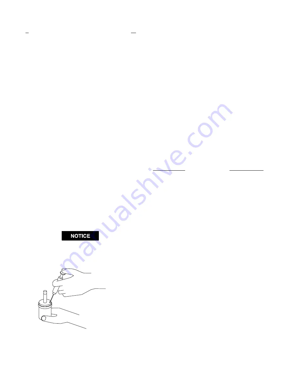
8.
Using the syringe and fluid from the Fluid
Replacement Kit (Part Number EQ106S–K400), fill
the mechanism with the fluid furnished in the Kit.
(Refer to Dwg. TPD1265).
DO NOT SUBSTITUTE ANY OTHER FLUID.
Failure to use the fluid provided could damage the
tool, increase maintenance and decrease
performance. Use only clean fluid in these tools.
(Dwg. TPD1265)
9. Submerge the fill opening in the remainder of the
fluid, and using a wrench, rotate the Drive Shaft to
purge any remaining air from the system.
10. Thread the Oil Plug with the Oil Plug Seal into the
mechanism until it is snug.
11. Using the 1.5 mm Hex Wrench, turn the Torque
Adjustment Screw clockwise until it stops. This is
the maximum torque position.
12. Wipe the outside of the mechanism dry and clean and
remove the Oil Chamber Plug. Using the syringe,
withdraw 0.3 cc of fluid.
13. Install the Oil Chamber Plug and tighten it between
20 and 25 in–lb (2.3 and 2.8 Nm) torque.
14. Place the mechanism on the hex hub of the Planetary
Gear Frame (23) and install the Mechanism Cover
over the Drive Shaft against the Motor Housing.
Install the four Mechanism Cover Mounting Screws.
15. For Model BP10PQ1, insert the Bit Retaining Ball
into the hole in the Drive Shaft. Install the Bit
Retaining Sleeve, Retaining Sleeve Spring and Spring
Seat on the output end of the Drive Shaft. While
compressing the Spring with the Seat, install the
Retaining Ring in the groove on the Shaft.
DISASSEMBLY
General Instructions
1.
Do not disassemble the tool any further than
necessary to replace or repair damaged parts.
2.
When grasping a tool or part in a vise, always use
leather–covered or copper–covered vise jaws to
protect the surface of the part and help prevent
distortion. This is particularly true of threaded
members and housings.
3.
Do not remove any part that is a press fit in or on an
assembly unless the removal of that part is necessary
for repairs or replacement.
4.
Do not disassemble the tool unless you have a
complete set of new gaskets and O–rings for
replacements.
Disassembly of the Impulse Mechanism
1.
Remove the Battery (71) from the tool.
2.
For Model BP10PQ1, use a pointed probe to push
the Spring Seat (48) against the Retaining Sleeve
Spring (47). While the Spring is compressed, use
another pointed probe or thin blade screwdriver to
remove the Retaining Ring (49). Lift the Spring Seat,
Spring and Bit Retaining Sleeve (46) off the Drive
Shaft (44) and remove the Bit Retaining Ball (45).
For Model BP10P3, use a hooked wire to pull the
Retaining Pin Spring (52) out of the end of the Drive
Shaft (50) and remove the Socket Retaining Pin (51).


