background image

6

ACC-SVN91G-EN

Installation

W

WA

AR

RN

NIIN

NG

G

R

Ro

otta

attiin

ng

g C

Co

om

mp

po

on

ne

en

nttss!!

F

Fa

aiillu

urre

e tto

o d

diisscco

on

nn

ne

ecctt p

po

ow

we

err b

be

effo

orre

e sse

errv

viicciin

ng

g cco

ou

ulld

d

rre

essu

ulltt iin

n rro

otta

attiin

ng

g cco

om

mp

po

on

ne

en

nttss ccu

uttttiin

ng

g a

an

nd

d sslla

assh

hiin

ng

g

tte

ecch

hn

niicciia

an

n w

wh

hiicch

h cco

ou

ulld

d rre

essu

ulltt iin

n d

de

ea

atth

h o

orr sse

erriio

ou

uss

iin

njju

urry

y..

D

Diisscco

on

nn

ne

ecctt a

allll e

elle

eccttrriicc p

po

ow

we

err,, iin

nccllu

ud

diin

ng

g rre

em

mo

otte

e

d

diisscco

on

nn

ne

eccttss b

be

effo

orre

e sse

errv

viicciin

ng

g.. F

Fo

ollllo

ow

w p

prro

op

pe

err

llo

occkko

ou

utt//tta

ag

go

ou

utt p

prro

occe

ed

du

urre

ess tto

o e

en

nssu

urre

e tth

he

e p

po

ow

we

err

cca

an

n n

no

ott b

be

e iin

na

ad

dv

ve

errtte

en

nttlly

y e

en

ne

errg

giizze

ed

d..

N

No

otte

e:: All phases of this installation must comply with

national, state, and local codes.

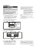
1. Remove duct flange from around air discharge on

top of the air handler. Retain screws and flange for
(optional) installation on top of the heater. See

Figure 1, p. 6

and

Figure 2, p. 6

.

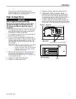
2. Remove the control wire knockout (Knockout #1)

from top of air handler and insert plastic bushing
supplied with heater. This knockout will also be
used if single point power entry is utilized.

IIm

mp

po

orrtta

an

ntt:: For ventilation purposes, Heaters

L112A, L117A, L123A, L129A, L325A,
and L335A require that an additional
knockout (knockout #2) be removed
(see

Figure 1, p. 6

). When using

BAYHTRL325A with a TWE060*3 (5 ton)
air handler, the heater baffle must be
removed (see

Figure 3, p. 7

).

3. Remove air handler access panel and control box

cover.

N

No

otte

e:: Apply gasket to heater see heater gasket

installation sheet.

4. Place heater on air handler and secure in place with

the screws provided.

Figure 1.

Top of air handler single blower

Figure 2.

Top of air handler dual blower

Low Voltage Wires (24 Volts)

1. For Heaters with single stage heat, there will be 1

brown wire and 1 black wire.

2. For Heaters with two stage heat, there will be 1

brown wire, 1 black wire and 1 orange wire.

3. Route the 2 or 3 low voltage wires down through

the plastic bushing in the knockout #1 to the low
voltage terminal block see

Figure 4, p. 8

and

Figure

5, p. 9

Wire according to heater wiring diagram.

4. Wire ties and cable clamps supplied should be used

Summary of Contents for BAYHTRL

Page 1: ...uipment by an unqualified person could result in death or serious injury When working on the equipment observe all precautions in the literature and on the tags stickers and labels that are attached to the equipment August 2017 A AC CC C S SV VN N9 91 1G G E EN N Electric Heaters Split System Air Handlers 5 25 Ton B BA AY YH HT TR RL L Used with TWE051 TWE060 TWE072 TWE076 TWE090 TWE101 TWE120 TWE...

Page 2: ...jo ob b b be ei in ng g u un nd de er rt ta ak ke en n c co ou ul ld d r re es su ul lt t i in n d de ea at th h o or r s se er ri io ou us s i in nj ju ur ry y T Te ec ch hn ni ic ci ia an ns s i in n o or rd de er r t to o p pr ro ot te ec ct t t th he em ms se el lv ve es s f fr ro om m p po ot te en nt ti ia al l e el le ec ct tr ri ic ca al l m me ec ch ha an ni ic ca al l a an nd d c ch he e...

Page 3: ...l li ic ci ie es s c ca an n b be e f fo ou un nd d o on n t th he e B BO OS S s si it te e W Wh he er re e l lo oc ca al l r re eg gu ul la at ti io on ns s a ar re e m mo or re e s st tr ri in ng ge en nt t t th ha an n t th he es se e p po ol li ic ci ie es s t th ho os se e r re eg gu ul la at ti io on ns s s su up pe er rs se ed de e t th he es se e p po ol li ic ci ie es s N No on n I In ng ...

Page 4: ...4 ACC SVN91G EN Pre Installation 5 Inspection 5 General 5 Parts List 5 Installation 6 Low Voltage Wires 24 Volts 6 High Voltage Wires 7 Wiring Diagrams 10 Table of Contents ...

Page 5: ... clamps 2 screws for cable clamp 2 bullet wire ties 4 regular wire ties 1 plastic bushing 11 screws for the L series heaters 20 screws for the M series heaters 1 gasket Table 1 Heater compatibility L and M series Unit Model Voltage a b Phase Heaters L Series TWE060 1 208 230 1 ph BAYHTRL106A 112A 117A 123A TWE060 3 208 230 3 ph BAYHTRL305A 310A 315A 325A TWE051 TWE060 4 380V 50Hz 460V 60Hz 3 ph BA...

Page 6: ...ge on top of the air handler Retain screws and flange for optional installation on top of the heater See Figure 1 p 6 and Figure 2 p 6 2 Remove the control wire knockout Knockout 1 from top of air handler and insert plastic bushing supplied with heater This knockout will also be used if single point power entry is utilized I Im mp po or rt ta an nt t For ventilation purposes Heaters L112A L117A L1...

Page 7: ... be hard wired to the bottom contacts of the air handler contactor per the wiring diagram for the standard air handlers For the 2 speed VFD and SZVAV the wires connect to the fuse block I Im mp po or rt ta an nt t When the dual point power entry option is used the high voltage wires for single point power entry should remain capped coiled up and clamped inside the heater control box 4 When using d...

Page 8: ...ection device values 2 For single point power entry option heater blower motor see the heater installed nameplate on the air handler for MCA and over current protection device values 3 When electric heater accessory is used single point power entry or dual point power entry is field optional Single point power entry option is through electric heater only I In ns st ta al ll la at ti io on n ...

Page 9: ...ction device values 2 For single point power entry option heater blower motor see the heater installed nameplate on the air handler for MCA and over current protection device values 3 When electric heater accessory is used single point power entry or dual point power entry is field optional Single point power entry option is through electric heater only I In ns st ta al ll la at ti io on n ...

Page 10: ...10 ACC SVN91G EN Wiring Diagrams The following diagrams can be accessed through e Library or a local sales office Figure 6 BAYHTRL106A 4367 0380 ...

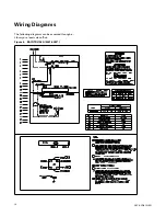
Page 11: ...ACC SVN91G EN 11 Figure 7 BAYHTRL112A 4367 0381 W Wi ir ri in ng g D Di ia ag gr ra am ms s ...

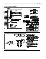
Page 12: ...12 ACC SVN91G EN Figure 8 BAYHTRL117A 4367 0324 W Wi ir ri in ng g D Di ia ag gr ra am ms s ...

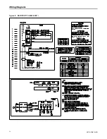
Page 13: ...ACC SVN91G EN 13 Figure 9 BAYHTRL123A 4367 0382 W Wi ir ri in ng g D Di ia ag gr ra am ms s ...

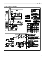
Page 14: ...14 ACC SVN91G EN Figure 10 BAYHTRL129A 4367 0383 W Wi ir ri in ng g D Di ia ag gr ra am ms s ...

Page 15: ...ACC SVN91G EN 15 Figure 11 BAYHTRL305A 310A 4367 0369 W Wi ir ri in ng g D Di ia ag gr ra am ms s ...

Page 16: ...16 ACC SVN91G EN Figure 12 BAYHTRM430 W30 4367 0386 W Wi ir ri in ng g D Di ia ag gr ra am ms s ...

Page 17: ...ACC SVN91G EN 17 Figure 13 BAYHTRM450 W50 4367 0385 W Wi ir ri in ng g D Di ia ag gr ra am ms s ...

Page 18: ...18 ACC SVN91G EN Figure 14 BAYHTRM350 4367 0348 W Wi ir ri in ng g D Di ia ag gr ra am ms s ...

Page 19: ...ACC SVN91G EN 19 Figure 15 BAYHTRM330 4367 0384 W Wi ir ri in ng g D Di ia ag gr ra am ms s ...

Page 20: ...nd protect food and perishables and increase industrial productivity and efficiency We are a global business committed to a world of sustainable progress and enduring results ingersollrand com Ingersoll Rand has a policy of continuous product and product data improvements and reserves the right to change design and specifications without notice We are committed to using environmentally conscious p...

Reviews: