88-A952V001-1C-EN
59
Electrical Connections
0DNH ZLULQJ FRQQHFWLRQV WR WKH XQLW DV LQGLFDWHG RQ HQFORVHG ZLULQJ GLDJUDP $V ZLWK DOO JDV DSSOLDQFHV XVLQJ HOHFWULFDO SRZHU WKLV IXUQDFH VKDOO
EH FRQQHFWHG LQWR D SHUPDQHQWO\ OLYH HOHFWULF FLUFXLW ,W LV UHFRPPHQGHG WKDW IXUQDFH EH SURYLGHG ZLWK D VHSDUDWH FLUFXLW SURWHFWLRQ GHYLFH
HOHFWULF FLUFXLW 7KH IXUQDFH PXVW EH HOHFWULFDOO\ JURXQGHG LQ DFFRUGDQFH ZLWK ORFDO FRGHV RU LQ WKH DEVHQFH RI ORFDO FRGHV ZLWK WKH 1DWLRQDO
(OHFWULFDO &RGH $16,1)3$ RU &6$ & (OHFWULFDO &RGH LI DQ H[WHUQDO HOHFWULFDO VRXUFH LV XWLOL]HG
7KH LQWHJUDWHG IXUQDFH FRQWURO LV
SRODULW\ VHQVLWLYH
7KH KRW OHJ RI WKH 9 SRZHU VXSSO\ PXVW EH FRQQHFWHG WR WKH EODFN SRZHU OHDG DV LQGLFDWHG RQ WKH ZLULQJ GLDJUDP
5HIHU WR WKH 6(59,&( )$&76 OLWHUDWXUH DQG XQLW ZLULQJ GLDJUDP DWWDFKHG WR IXUQDFH
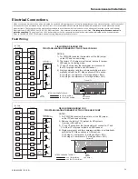
Field Wiring
O
BK
BK
Y2
Y1
Y1
B/C
B/C
W2
W1
W1
G
G
R
R
O
Y1
B/C
Two Stage
Thermostat
Furnace
Furnace IFC
Outdoor Unit
(No Transformer)
SEE
NOTE 2
BK JUMPER
SEE NOTE 1
Y2
W2
Y2
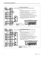
FIELD WIRING DIAGRAM FOR
TWO STAGE HEATING THERMOSTAT, TWO STAGE COOLING
NOTES:
1) For PWM (BK) enabled thermostats, cut the BK jumper
on the IFC and connect wiring.
2) The factory Y1-O jumper must remain in place for proper
LED read out in cooling mode.
3) Y1 and Y2 wiring from the thermostat must connect to
the IFC for proper airflow and LED readout.
4) Single compressor and two compressor airflow is auto-
matically set with the IFC Menu optionsin ODU section.
2-1=2 stage / 1 compressor (1st stage airflow = 80%)
2-2=2 stage / 2 compressors (1st stage airflow = 50%)
INTER-COMPONENT WIRING
24 V FIELD WIRING
24 V FACTORY WIRING
O
BK
BK
Y2
Y1
Y1
B/C
B/C
W2
W2
W1
W1
G
G
R
R
O
Y1
Two Stage
Thermostat
Furnace
Outdoor Unit
(No Transformer)
SEE
NOTE 2
O
R
X2
Y2
NOTES:
1) For PWM (BK) enabled thermostats, cut the BK jumper
on the IFC and connect wiring.
2) Remove the factory Y1-O jumper for HP systems
for proper LED read out.
3) Y1 and Y2 wiring from the thermostat must connect to Y1 and
Y2 of the IFC for proper airflow and LED readout.
4) Single compressor and two compressor airflow is automatically
set with the IFC Menu options in ODU section.
2-1=2 stage / 1 compressor (1st stage airflow = 80%)
2-2=2 stage / 2 compressors (1st stage airflow = 50%)
INTER-COMPONENT WIRING
24 V FIELD WIRING
24 V FACTORY WIRING
R-BK
JUMPER
SEE NOTE 1
Furnace IFC
FIELD WIRING DIAGRAM FOR
TWO STAGE HEATING THERMOSTAT, TWO STAGE HEAT PUMP
Y2
B/C
F
Fu
urrn
na
acce
e G
Ge
en
ne
erra
all IIn
nsstta
alllla
attiio
on
n

