2
04584355_ed3
Product Safety Information
WARNING
Failure to observe the following warnings, and to avoid these potentially hazardous situations, could result in death or serious
injury.
Read and understand this and all other supplied manuals before installing, operating, repairing, maintaining, changing accessories
on, or working near this product.
Always wear eye protection when operating or performing maintenance on this tool. The grade of protection required should be
assessed for each use and may include impact-resistant glasses with side shields, goggles, or a full face shield over those glasses.
Always turn off the air supply, bleed the air pressure and disconnect the air supply hose when not in use, before installing, removing
or adjusting any accessory on this tool, or before performing any maintenance on this tool or any accessory.
Note:
When reading the instructions, refer to exploded diagrams in Parts Information Manuals when applicable (see under Related Documentation
for form numbers).
Lubrication
•
•
•
•
Each time a Series 2925B2Ti Impactool is disassembled for
maintenance and repair or replacement of parts, lubricate the tool
as follows:
1. Work approximately 12 to 15 cc of Ingersoll Rand No. 170
Grease into the impact mechanism. Coat the Anvil (40) lightly
with grease around the Hammer Case Bushing (42). Inject
approximately 2 to 4 cc of grease into the Grease Fitting (18).
2. Use Ingersoll Rand No. 10 Oil for lubricating the motor.
Inject approximately 1 to 2 cc of oil into the air inlet before
attaching the air hose.
Disassembly
General Instructions
1. Do not disassemble the tool any further than necessary to replace
or repair damaged parts.
2. Whenever grasping a tool or a part in a vise, always use leather-
covered or copper-covered vise jaws to protect the surface of
the part and help prevent distortion. This is particularly true of
threaded members and housings.
3. Do not remove any part which is a press fit in or on a
subassembly unless the removal of that part is necessary for
repair or replacement.
4. Do not disassemble the Impactool unless you have a complete
set of new gaskets and o-rings for replacement.
Disassembly of the Hammer Case and Anvil Assembly
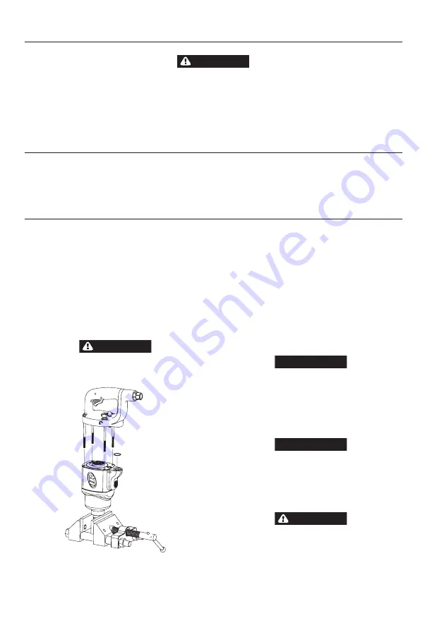
WARNING
Before disassembling this tool, clamp the anvil drive in
leather-covered or copper-covered vise jaws with the
Handle (1) pointing upward. See Drawing TPD2021-1.
(Dwg. TPD2021-1)
1. Unscrew and remove the four Handle Bolts (2).
2. Lift the assembled Motor Housing (30) off of the Hammer Case
(43). Make sure that you hold the Backcap in position on the
Housing and that the motor does not come out of the Housing.
3. Remove the Hammer Case Gasket (41) and replace with a new
one when assembling the Hammer Case to the Housing.
4. Remove the Hammer Case and impact mechanism assembly from
the vise. Remove the Hammer Frame Washer (36) from the rear of
the Hammer Frame and set it aside on a clean bench.
5. Place the impact mechanism on a bench with the Anvil pointing
upward. Make sure that the Hammer Pins (38) do not drop out of
the Hammer.
6. Lift the Hammer Case off of the Anvil (40). If it is unnecessary to
disassemble the impact mechanism, set it aside intact.
Disassembly of the Impact Mechanism
1. Set the mechanism, driver end up, on the workbench.
NOTICE
Note the twin Hammers within the Hammer Frame. These are
identical but must be placed in the Hammer Frame in a particular
relationship. Using a felt tipped pen, mark the top Hammer “T
↑
”
and the bottom Hammer “B
↑
” with arrows pointing upward.
Mark both Hammers on same end.
2. With the mechanism sitting upright on the workbench, slowly
rotate the Anvil in a clockwise direction until it comes up solid.
NOTICE
If you continue to rotate the Anvil, it will cam the Hammers out
of engagement. Do not do this; merely rotate the Anvil until it
comes up solid.
3. Hold the Hammer Frame firmly and, without disturbing the
Hammers, gently lift the Anvil, simultaneously rotating it
clockwise about 1/8 of a turn, from the Hammer Frame.
4. With the Anvil removed, lift out the two Hammer Pins.
CAUTION
The twin Hammers are now free to slide from the Hammer
Frame. Be careful not to drop them.
Disassembly of the Reverse Valve
1. Remove the four Handle Bolts (2)
2. Lift the Handle (1) off of the rear of the Motor Housing (30).
3. Discard the Handle Gasket (19) and replace it with a new one
when assembling the tool.
Summary of Contents for 2925B2Ti
Page 6: ...Notes...
Page 7: ...Notes...


