


2
16605883_ed2
Product Safety Information
WARNING
Failure to observe the following warnings, and to avoid these potentially hazardous situations, could result in death or serious
injury.
Read and understand this and all other supplied manuals before installing, operating, repairing, maintaining, changing accessories
on, or working near this product.
Always wear eye protection when operating or performing maintenance on this tool. The grade of protection required should be
assessed for each use and may include impact-resistant glasses with side shields, goggles, or a full face shield over those glasses.
Always turn off the air supply, bleed the air pressure and disconnect the air supply hose when not in use, before installing, removing
or adjusting any accessory on this tool, or before performing any maintenance on this tool or any accessory.
Note:
When reading the instructions, refer to exploded diagrams in parts Information Manuals when applicable (see under Related Documentation
for form numbers).
Lubrication
•
•
•
•
Each time a Model 132 Air Hammer is disassembled for
maintenance, repair or replacement of parts, lubricate the
tool as follows:
Inject several drops of Ingersoll Rand No. 10 Oil into the air inlet and
operate the tool for 5 seconds to coat the internal parts with oil.
Disassembly
General Instructions
Do not disassemble the tool any further than necessary to replace
or repair damaged parts.
Whenever grasping a tool or part in a vise, always use leather-
covered or copper-covered vise jaws to protect the surface of
the part and help prevent distortion. This is particularly true of
threaded members and housings.
Do not remove any part which is a press fit in or on a subassembly
unless the removal of that part is necessary for repairs or
replacement.
Do not disassemble the tool unless you have a complete set of
new gaskets and O-rings for replacement.
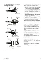
Disassembly of the Tool
Clamp the Handle (1) in leather-covered or copper-covered vise
jaws with the accessory end upward.
Remove the Tool Retainer (25 or 25A) and any accessory from the
Barrel (24).
Remove the Exhaust Deflector (22) from the Barrel.
Remove the Locking Key (21) that keeps the Barrel from
unscrewing from the Handle Assembly.
Carefully unscrew the Barrel from the Handle Assembly.
Remove the Piston (23) and the Valve Box Assembly.
1.
2.
3.
4.
1.
2.
3.
4.
5.
6.
Disassembly of the Throttle Mechanism
Clamp the Handle in leather-covered or copper-covered vise jaws
with the Air Inlet Bushing (17) upward.
Remove the Throttle Adjuster Body (10).
Unscrew the Throttle Adjuster Cap Screw (16) and remove the
Throttle Adjuster Knob (14), Throttle Adjuster Stop Ball (13),
Throttle Adjuster Stop Spring (12), and the Throttle Adjuster
Sleeve (15).
Remove the Throttle Adjuster Screw (11), the Throttle Valve
Spring (9), and the Throttle Valve Assembly (5) from the Handle.
Remove the Air Inlet Bushing.
Rotate the Handle in the vise to gain access to the Intermediate
Lever Pin (4). Drive out the Pin.
Carefully remove the Trigger (2) and the Intermediate Lever (3).
Disassembly of the Valve Box Assembly
Separate the two halves of the Valve Box Assembly. A small brass
or plastic hammer may be needed to gently tap the Valve
Box (18) apart.
Carefully remove the Dowel Pin (19) and the Valve (20).
1.
2.
3.
4.
5.
6.
7.
1.
2.
Assembly
General Instructions
Whenever grasping a tool or part in a vise, always use
leather-covered or copper-covered vise jaws. Take extra care with
threaded parts and housings.
1.
Always clean every part and wipe every part with a thin film of oil
before installation.
Apply a film of O-ring lubricant to all O-rings before final
assembly.
2.
3.
Summary of Contents for 132
Page 5: ...Notes ...
Page 6: ...Notes ...
Page 7: ...Notes ...
Page 8: ...ingersollrandproducts com 2014 Ingersoll Rand ...