background image

OPTIONS

47

9/230, 9/270, 9/300,  12/235, 17/235, 21/215, 9/230HA, 9/270HA, 9/300HA,  12/235HA, 17/235HA, 21/215HA

IQ SYSTEM


OPERATING INSTRUCTIONS – 1

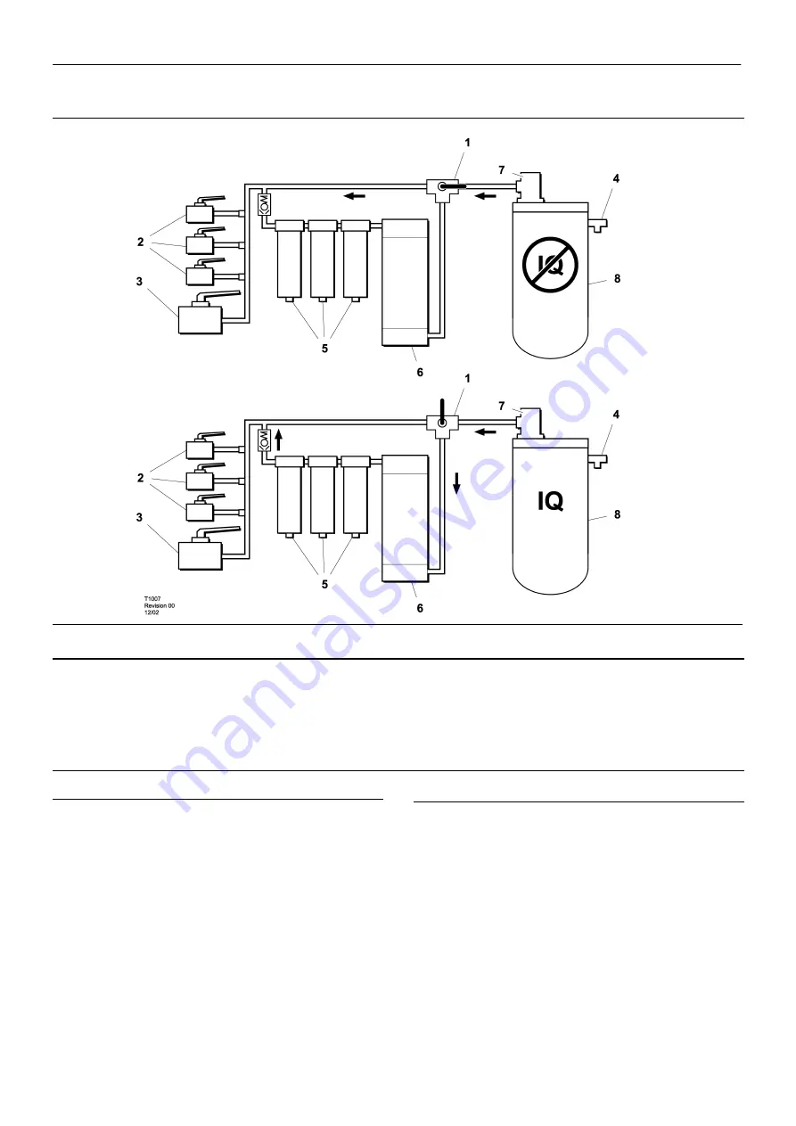
KEY

1

Three way valve

2

Ball valve1

1

/

4

3

Ball valve2”

4

Safety valve

5

Filters

6

Aftercooler

7

Minimum pressure valve

8

Separator tank

IQ SYSTEM

The IQ System is a complete, self–contained system which

provides cooler, cleaner air than from a standard portable
compressor.  The system utilizes an integral aftercooler,
high–efficiency filtration, and a patented condensate disposal system
to provide the cool, clean air.  The condensate disposal system
injects all liquid condensed from the moisture separator and filters
into the engine exhaust system where it is vaporized by heat.  This
eliminates the need for collecting the condensate, and the added
cost of disposing of the condensate, which is often regulated by
local, state, and/or federal regulations.

When equipped with the low ambient feature, the IQ System

automatically adjusts movable louvers to control airflow through the
aftercooler, ensuring that the compressed air temperature always
remains above freezing temperatures (typically 45

F) at any ambient

temperature down to –20

F.  This prevents the need for 120V AC

heat tracing systems, or any manual adjustment to prevent freezing
of the compressed air system.  All drain points for the condensate
handling system are heated with 24VDC heaters, which are integral
to the compressor heater system.
Standard Non–Louvered configuration not to be operated below
freezing. 

IQ SYSTEM


OPERATING INSTRUCTIONS – 2

The compressed air exits the separator tank through the top

cover piping, and can then travel along one of two paths, selectable
via manual valving.

One path allows Standard Operation, which bypasses the IQ

System, and delivers air quality equivalent to a standard oil–flooded
portable compressor.  If the IQ System is enabled by proper setting
of the selector valve, the compressed air first enters the aftercooler.

The aftercooler is cooled by the incoming compressor package

air, which is controlled by movable louvers mounted on the
aftercooler (if equipped with low ambient option).  At most conditions,
the louvers are fully open, and maximum aftercooling is available.
The compressed air and condensate (water with a small amount of
compressor lubricant) exits the aftercooler and enters the moisture
separator, where most of the condensate is removed.  The
compressed air then flows through two stages of filtration, where the
aerosol water and oil is removed down to approximately 0.01 ppm,
and all particulates are removed down to 0.01 micron.

Summary of Contents for 12/235

Page 1: ...8 GB DATE MARCH 2003 892000 IR 17 235 SERIAL No 881000 9 300 12 335 21 215 Revised 10 12 Doosan purchased Bobcat Company from Ingersoll Rand Company in 2007 Any reference to Ingersoll Rand Company or use of trademarks service marks logos or other proprietary identifying marks belonging to Ingersoll Rand Company in this manual is historical or nominative in nature and is not meant to suggest a curr...

Page 2: ...92 EN60204 1 EN1012 1 PN8NTC2 EN50081 EN50082 ________________________________ 9 230 9 270 9 300 12 235 17 235 21 215 Ric Lunsford Manager of quality control DECLARATION OF CONFORMITY WITH EC DIRECTIVES CONFORMITY WITH NOISE DIRECTIVE 2000 14 EC Ingersoll Rand Company Limited declare that the following Portable Compressors have been manufactured in conformity with the directive as shown Machine Se...

Page 3: ...ntenance Lubrication Speed pressure regulation Torque settings table Compressor lubrication 40 MACHINE SYSTEMS Electrical system Piping instrumentation system 45 FAULT FINDING 47 OPTIONS 49 PARTS ORDERING ABBREVIATIONS SYMBOLS Contact Ingersoll Rand for serial number Up to Serial No From Serial No Not illustrated Option WDG Generator option AR As required BR Brazil CN China DE Germany DK Denmark E...

Page 4: ...to the compressed air system should be of good quality procured from a reputable manufacturer and wherever possible be of a type approved by Ingersoll Rand clearly rated for a pressure at least equal to the machine maximum allowable working pressure compatible with the compressor lubricant coolant accompaniedwith instructions for safe installation operation and maintenance Details of approved equi...

Page 5: ...ect human consumption without suitable filtration and purity checks Use of the machine outside the ambient temperature range specified in the GENERAL INFORMATION SECTION of this manual Use of the machine where there is any actual or foreseeable risk of hazardous levels of flammable gases or vapours Use of the machine fitted with non Ingersoll Rand approved components lubricants fluids Use of the m...

Page 6: ...y Platinum drive train refers to the Ingersoll Rand Engine and Airend combination The earlier of sixty 60 months from shipment to or the accumulation of 10 000 hours of operationby the initial user The starter alternator fuel injection system and all electrical components are excluded from this extended warranty The airend seal and drive coupling are included in the warranty but airend drive belts...

Page 7: ...METAL ELECTRICAL CIRCUIT ETC ALTERNATOR 12 MONTHS 2 000 HOURS EXTENDED WARRANTY OF 24 MONTHS 4 000 HRS FOR LIGHTSOURCE INTRODUCED 8 16 99 ENGINE SEE BELOW ENGINES MONTHS HOURS COMMENTS CATERPILLAR 12 UNLIMITED EXTENDED WARRANTY PROVIDED VIA ENGINE SUPPLIER S OWN APPROVED NETWORK AT TIME OF PURCHASE CUMMINS 24 2 000 EXTENDED WARRANTY PROVIDED VIA ENGINE SUPPLIER S OWN APPROVED NETWORK AT TIME OF PU...

Page 8: ... MITSUBISHI 24 2 000 2YRS 4 000 HRS USING IR FLUIDS AND FILTERS VOLVO 24 2 000 2YRS 4 000 HRS USING IR FLUIDS AND FILTERS PARTS MONTHS HOURS COMMENTS INGERSOLL RAND 6 UNLIMITED PARTS ONLY AVAILABLE FROM IR NETWORK AIREND EXCHANGE MONTHS HOURS COMMENTS AIREND 12 2 000 24 MONTHS 4 000 HRS AVAILABLE FROM IR NETWORK CONSTRUCTION TOOLS MONTHS HOURS COMMENTS CONSTRUCTION TOOLS 12 N A OPTIONAL 36 MONTHS ...

Page 9: ...e optional warranty is limited to defects in major components rotors housings gears and bearings and is automatically available when the following conditions are met 1 The original airend is returned assembled and unopened 2 Submissions of proof that Ingersoll Rand fluid filters and separators have been used Refer to the Operation and Parts manual for the correct fluids filters and separator eleme...

Page 10: ...gan Lancashire WN2 4EZ U K Attn Customer Service Department Note Completion of this form validates the warranty Engine Registration I R powered machines do not require separate engine registration Deutz require a separate engine registration form to be completed and mailed direct to their Cologne office The form is supplied as part of the machine documentationfor Deutz powered machines Caterpillar...

Page 11: ...stration Form in this section keep a copy for your records and mail form to Ingersoll RandCompany P O Box 868 Mocksville North Carolina 27028 Attn Warranty Department Note Completion of this form validates the warranty Engine Registration I R powered machines do not require separate engine registration John Deere requires a separate engine registration be completed and mailed direct to John Deere ...

Page 12: ...TION FORM Customer Details Service Provider Details Company Name Service Provider Distributor Contact Name Branch Office Signature Company Address Machine Details Product Type Model Serial Number Engine Serial Number Engine Model Number Post Zip Code Airend Serial Number Country Alternator Serial Number Phone Number Date of start up Fax Number e mail ...

Page 13: ...t surface WARNING Pressure control WARNING Corrosion risk WARNING Air gas flow or Air discharge X XBAR WARNING Pressurised vessel WARNING Hot and harmful exhaust gas WARNING Maintain correct tyre pressure Refer to the GENERAL INFORMATION section of this manual 0 C WARNING Flammable liquid WARNING Before connecting the tow bar or commencing to tow consult the operation and maintenance manual WARNIN...

Page 14: ... the compressed air from this machine Do not remove the Operating and Maintenance manual and manual holder from this machine Do not stack Do not operate the machine without the guard being fitted Do not stand on any service valve or other parts of the pressure system Do not operate with the doors or enclosure open Do not use fork lift truck from this side XX km h Do not exceed the trailer speed li...

Page 15: ...0HA 9 270HA 9 300HA 12 235HA 17 235HA 21 215HA Lifting point On power Off power Read the Operation and Maintenance manual before operation or maintenance of this machine is undertaken When parking use prop stand handrake and wheel chocks Compressor oil filling ...

Page 16: ...ccidently be pressurised over pressurised by another Compressed air must not be used for a direct feed to any form of breathing apparatus or mask The discharged air contains a very small percentage of compressor lubricating oil and care should be taken to ensure that downstream equipmentis compatible If the discharged air is to be ultimately released into a confined space adequate ventilation must...

Page 17: ...ing machines ensure that the towing vehicle its size weight towing hitch and electrical supply are all suitable to provide safe and stable towing at speeds either up to the legal maximum for the country in which it is being towed or as specified for the machine model if lower than the legal maximum Before towing the machine ensure that the tyres and towing hitch are in a serviceable condition the ...

Page 18: ...GENERAL INFORMATION ESA CE HA 16 9 230 9 270 9 300 12 235 17 235 21 215 9 230HA 9 270HA 9 300HA 12 235HA 17 235HA 21 215HA CE HA ...

Page 19: ... 120 120 120 120 120 COMPRESSOR Cooling system Oil Injection Oil capacity Litre 70 70 70 70 75 75 Maximum oil system temperature C 120 120 120 120 120 120 Maximum oil system pressure psi bar kPa 217 15 1500 217 15 1500 217 15 1500 217 15 1500 362 25 2500 362 25 2500 LUBRICATING OIL SPECIFICATION for SEE NOTE 1 the specified ambient temperatures ENGINE Type model 9 235 IR 6IRQ9AE 12 235 IR 6IRQ9AE ...

Page 20: ...ver cooler and pipework must be flushed clear of the first fill fluid and new Ingersoll Rand oil filters installed When this has been completed the following oils are approved a for ambient temperatures above 23 C SAE 10W API CF 4 CG 4 b for ambient temperatures below 23 C I R Performance 500 only SOUND LEVEL DATA W model A To Pneurop code PN8NTC2 Equivalent continuous sound pressure level Rated l...

Page 21: ...en selecting the working position of the machine ensure that there is sufficient clearance for ventilation and exhaust requirements observing any specified minimum dimensions to walls floors etc Adequate clearance needs to be allowed around and above the machine to permit safe access for specified maintenance tasks Ensure that the machine is positioned securely and on a stable foundation Any risk ...

Page 22: ...iesel fuel oil with a minimum octane number of 45 and a sulphur content not greater than 0 5 CAUTION When refuelling switch off the engine do not smoke extinguish all naked lights do not allow the fuel to come into contact with hot surfaces wear personal protective equipment 5 Drain fuel filter water separator of water ensuring that any released fuel is safely contained 6 Check the radiator coolan...

Page 23: ...lamp Indicates shutdown due to compressor system fault Refer to Fault Code List 10 Low Battery Voltage Alarm indicator lamp Indicates battery or charging system requires service 11 Engine Malfunction Engine Fault code Refer to service card or engine manual for codes and service requirements 12 Malfunction Code 4 Digit Compressor or engine fault Refer to manual for list of codes and service require...

Page 24: ...PRSR Malfunction 30 Engine Crank Time Exceeded 3 CPRSR Malfunction 0 Engine Oil Temperature 252 deg F 5 CPRSR Malfunction Intake Manifold Temperature 180 deg F 6 CPRSR Malfunction Water In Fuel 8 CPRSR Malfunction Engine Not Responding To Throttle command 10 CPRSR Malfunction Engine Shut Itself Down reason unknown 29 CPRSR Malfunction Low AE Oil Pressure HP 1600 Only 31 CPRSR Malfunction 20 Disch ...

Page 25: ...PRSR Malfunction 3 Minimum Pressure Not Met 56 CPRSR Malfunction Engine Not Going To Max RPM Prior To Load 57 CPRSR Malfunction Serial Comm Problem 70 CPRSR Malfunction CAN Bus Problem 71 CPRSR Malfunction Dedicated Lights Low Fuel Level Fuel Level Fuel Level 3 Air Filter Restriction Soiled Filter Low Battery Voltage Battery Charging Condition Engine Oil Pressure 18 PSI Low Engine Oil Pressure Low...

Page 26: ...y 148 8 Accelerator Pedal Position Sensor Circuit high frequency 151 0 Engine Coolant Temperature High Critical 153 3 Intake Manifold Temperature Sensor 1 Circuit shorted high 154 4 Intake Manifold Temperature Sensor 1 Circuit shorted low 155 0 Intake Manifold Temperature 1 High Critical 184 2 Engine Control Module Identification Input State Error 211 11 Additional OEM Vehicle Diagnostic Codes hav...

Page 27: ...wer Interrupt 328 7 Fuel Pumping Element 2 Rear mechanically stuck 329 14 Fuel System Leakage error 349 16 Transmission Output Shaft Tailshaft Speed High Warning 352 4 Sensor Supply Voltage 1 Circuit shorted low 381 11 Intake Air Heater Relay Enable 1 Circuit data incorrect 382 11 Intake Air Heater Relay Enable 2 Circuit data incorrect 385 3 OEM Sensor Supply Voltage Circuit shorted high 386 3 Sen...

Page 28: ... execute a lamp test The low engine oil pressure and low battery lamps will flash indicating proper communication between wedge and engine ECM Inlet heater Wait to start light Turn the key switch to on position 1 until the inlet heater warning light 13 extinguishes NOTE Position 2 is not used Turn the key switch to crank position 3 engine start position Release to on position 1 when the engine sta...

Page 29: ...n identify and correct the fault before attempting to re start If the machine has been switched off for reasons of safety then ensure that the machine can be operated safely before re starting Refer to the PRIOR TO STARTING and STARTING THE UNIT instructions earlier in this section before re starting the machine MONITORING DURING OPERATION Should any of the safety shut down conditions occur the un...

Page 30: ...eaner Precleaner Dumps C Fan Alternator Belts C Battery Connections Electrolyte C Tire Pressure and Surface C Wheel Lug Nuts C Hoses Oil Air Intake etc C Automatic Shutdown System C Air Cleaner System C Compressor heat exchanger exterior C Engine heat exchanger exterior C Fasteners Guards C Air Cleaner Elements R WI Disregard if not appropriate for this particular machine 1 or 3000 miles 5000km wh...

Page 31: ...ch Settings T Scavenger Orifice Related Parts C Oil Separator Element R Feed Pump Strainer Cleaning C Valve Clearance Check C Lights running brake turn CBT Pintle Eye Bolts CBT Brakes CBT C Brake linkage C Emergency stop T Fasteners C Running gear linkage G Safety valve C Running gear bolts 1 C Disregard if not appropriate for this particular machine 1 or 3000 miles 5000km whichever is the sooner ...

Page 32: ... 2 exterior CR Lubricator Fill C 2 Yrs 4 Yrs 6 Yrs Safety valve C Hoses R Separator tank 2 interior C Disregard if not appropriate for this particular machine 1 or 3000 miles 5000km whichever is the sooner 2 or as defined by local or national legislation C Check adjust clean or replace as necessary CBT check before towing CR Check and report D Drain G Grease R Replace T Test W I or when indicated ...

Page 33: ...ce work on a running machine ensure that the work carried out is limited to only those tasks which require the machine to run the work carried out with safety protection devices disabled or removed is limited to only those tasks which require the machine to be running with safety protection devices disabled or removed all hazards present are known e g pressurised components electrically live compo...

Page 34: ...tank cover plate Replace the compressor oil refer to LUBRICATION later in this section CAUTION Start the machine refer to PRIOR TO STARTING and STARTING THE UNIT in the OPERATING INSTRUCTIONS section of this manual and check for leakage before the machine is put back into service COMPRESSOR OIL COOLER AND ENGINE RADIATOR AIR CHARGE COOLER When grease oil and dirt accumulate on the exterior surface...

Page 35: ...working day At six month intervals drain any sediment or condensate that may have accumulated in the tank s FUEL FILTER WATER SEPARATOR The fuel filter water separator contains a filter element which should be replaced at regular intervals see the SERVICE MAINTENANCE CHART CHARGE COOLER PIPEWORK Inspect all hoses and clips on the charge cooler pipe work Engine damage will occur if the charge cooli...

Page 36: ...recommended intervals Refer to the SERVICE MAINTENANCE CHART COMPRESSOR LUBRICATING OIL Refer to the SERVICE MAINTENANCE CHART in this section for service intervals NOTE If the machine has been operating under adverse conditions or has suffered long shutdown periods then more frequent service intervals will be required WARNING DO NOT under any circumstances remove any drain plugs or the oil filler...

Page 37: ...ve A Adjusting screw Start the machine Refer to STARTING INSTRUCTIONS in the OPERATING INSTRUCTIONS section of this manual Adjust the service valve on the outside of the machine to maintain normal operating discharge pressure refer to GENERAL INFORMATION and full speed position If the tachometer moves away from the full speed position before normal operating discharge pressure is attained then tur...

Page 38: ... D and rotate the butterfly valve pivot shaft K fully clockwise until the valve is closed Position lever L approximately 10 after vertical and tighten screw D Keep the butterfly lever in the closed position and with the the air cylinder fully contracted tighten the screws holding bracket C to the main bracket J Allow the cylinder to return to its extended position and reconnect the ballast spring ...

Page 39: ... MARKING 8AE J249 GRADE 8 HEAD MARKING TYPICAL RECTANGULAR TORQUE PATTERN CAPSCREW OR NUT THREAD SIZE AND PITCH TYPICAL SQUARE TORQUE PATTERN Nm FT LBF Nm FT LBF 1 4 20 11 8 16 12 5 16 18 24 17 33 25 3 8 16 42 31 59 44 7 16 14 67 49 95 70 1 2 13 102 75 144 106 9 16 12 148 109 208 154 5 8 11 203 150 287 212 TYPICAL CIRCULAR TORQUE 3 4 10 361 266 509 376 TYPICAL CIRCULAR TORQUE PATTERN ...

Page 40: ...KING PROPERTY GRADE 12 9 HEAD MARKING TYPICAL RECTANGULAR TORQUE PATTERN CAPSCREW OR NUT THREAD SIZE AND PITCH TYPICAL SQUARE TORQUE PATTERN Nm FT LBF Nm FT LBF Nm FT LBF M6 X 1 0 11 8 15 11 18 13 M8 X 1 25 26 19 36 27 43 31 M10 X 1 5 52 38 72 53 84 62 M12 X 1 75 91 67 126 93 147 109 M14 X 2 145 107 200 148 234 173 M16 X 2 226 166 313 231 365 270 TYPICAL CIRCULAR TORQUE PATTERN M20 X 2 5 441 325 6...

Page 41: ...ce 500 Mil L 46167 500 psi 50 F to 125 F 10 C to 52 C 10 F to 65 F 12 C to 18 C below 10 F 12 C IR XHP1001 IR XHP 505 Consult Factory IR XHP505 IR XHP1001 IR PER FORMANCE 500 IR PRO TEC 100 300 PSI RATED OPERATING PRESSURE 350 PSI 500 PSI IR XHP 1001 IR 500 PERFORMANCE IR XHP505 10 F 125 F 50 C 40 C 30 C 20 C 10 C 0 C 10 C 20 C 30 C 40 C 104 F 86 F 65 F 50 F 32 F 14 F 10 F 22 F 40 F consult factor...

Page 42: ...MACHINE SYSTEMS 40 9 230 9 270 9 300 12 235 17 235 21 215 9 230HA 9 270HA 9 300HA 12 235HA 17 235HA 21 215HA ...

Page 43: ...warning beacon POUT4 Spare POUT5 Start relay POUT6 Start compressor POUT7 Hour meter POUT8 Solenoid unloader PT1 Pressure trancducer separator tank 0 225 PSIG 9 235 9 270 9 300 12 235 0 225 PSIG HP935 VHP750 MHP825 XP1060 0 500 PSIG 21 215 17 235 XHP750 PT2 Pressure trancducer regulation system 0 100 PSIG PM Plug machine ID RS Relay spst RT1 Thermistor seperator tank temperature 30 255 F RT2 Therm...

Page 44: ...at 24 VDC FREQ THT WEDGE CONTROLLER FREQ THT ENGINE ECM WEDGE TO ENGINE INTERFACE ENGINE ECM DIAGNOSTIC INTERFACE CONTROLL PANEL HARNESS SOLENOID VALVES 24VDC HEATERS GUAGES HOURMETER CONTROL PANEL SWITCHES WEDGE CONTROLLER SPEED SENSOR FUEL LEVEL SWITCH PRESSURE TRANSDUCER TEMPERATURE SENSOR BATTERY STARTING AND CHARGING SYSTEM ESTOP SWITCHES HARNESS SYSTEM SCHEMATIC ...

Page 45: ...RESTRICTION INDICATOR SWITCH 2 36870608 ENGIINE OIL PRESSURE SENDER 1 36841138 COMPRESSOR AND ENGIINE TEMPERATURE SENDER 2 36757581 COMPRESSOR OIL PRESSURE SWITCH 1 36850691 COMPRESSOR MOTOR 1 35577873 RELAY MAGNETIC 24V K1 1 36841526 CONTROL HEATER 2 26854677 REGULATOR HEATER 1 54658323 NEGATIVE BATTERY CABLE 1 54658331 POSITIVE BATTERY CABLE 1 54511282 POSITIVE JUMPER BATTERY CABLE 1 35128982 BA...

Page 46: ... VALVE 1 36847838 AIR FILTER RESTRICTION INDICATOR SWITCH 2 36870608 ENGIINE OIL PRESSURE SENDER 1 36841138 COMPRESSOR AND ENGIINE TEMPERATURE SENDER 2 36757581 COMPRESSOR OIL PRESSURE SWITCH 1 36850691 COMPRESSOR MOTOR 1 35577873 RELAY MAGNETIC 24V K1 1 36841526 CONTROL HEATER 2 54658323 NEGATIVE BATTERY CABLE 1 54658331 POSITIVE BATTERY CABLE 1 54511282 POSITIVE JUMPER BATTERY CABLE 1 35128982 B...

Page 47: ...emperature Check the compressor oil level and oil cooler Check the fan drive Water present in fuel system Check the water separator and clean if required Faulty relay Check the relay in the holder and replace if necessary Engine Overheats Low water level Check the level and replenish if necessary Blocked radiator Stop the machine and clean the cooling fins with compressed air or steam Use reduced ...

Page 48: ...RESSURE REGULATION ADJUSTMENT in the MAINTENANCE section of this manual Loose pipe hose connections Check all pipe hose connections Faulty safety valve Check the relieving pressure Replace the safety valve if faulty DO NOT ATTEMPT A REPAIR Oil is forced back into the air filter Incorrect stopping procedure used Always employ the correct stopping procedure Close the discharge valve and allow the ma...

Page 49: ...e need for 120V AC heat tracing systems or any manual adjustment to prevent freezing of the compressed air system All drain points for the condensate handling system are heated with 24VDC heaters which are integral to the compressor heater system Standard Non Louvered configuration not to be operated below freezing IQ SYSTEM OPERATING INSTRUCTIONS 2 The compressed air exits the separator tank thro...

Page 50: ...the control panel and will shut down the compressor if restriction exceeds recommended values Weekly Maintenance Remove Y strainer screens at the bottom of the moisture separator and both filters and clean out any residue Verify that the orifices below the Y strainers are not clogged Verify that the piping from the orifice purge points to the exhaust system is not clogged Yearly Maintenance The no...

Page 51: ...ions show each part distinctly and in location relative to the other parts in the assembly The part number the description of the part and the quantity of parts required are shown on each illustration or on adjacent page The quantities specified are the number of parts used per one assembly and are not necessarily the total number of parts used in the machine Where no quantity is specified the qua...

Page 52: ... of an offer is expressly limited to the exact terms contained herein If purchaser s order form is used for acceptance of an offer it is expressly understood and agreed that the terms and conditions of such order form shall not apply unless expressly agreed to by Ingersoll Rand Company Company in writing No additional or contrary terms will be binding upon the Company unless expressly agreed to in...

Page 53: ...nterest lost goodwill work stoppage impairment of other goods loss by reason of shutdown or non operation increased expenses of operation or claims of customers of Purchaser for service interruption whether or not such loss or damage is based on contract warranty negligence indemnity strict liability or otherwise AIREND EXCHANGE PROGRAM Ingersoll Rand offers an airend exchange program to benefit p...

Page 54: ...860 6863 Asia Pacific Fax 336 751 1579 US Canada 336 751 4325 Latin America 336 751 4325 Asia Pacific Facility Office hours Monday Friday 8 00 a m to 5 30 p m EST Telephone 44 0 1942 257 171 Fax 44 0 1942 523 417 Facility Office hours Monday Friday 8 00 a m to 4 30 p m GMT For information on how to order parts or information regarding your local distributor Europe Middle East Africa please contact...

Page 55: ......

Page 56: ......

Page 57: ...Printed in the United Kingdom ...

Reviews: