background image

Operating & Maintenance Manual

Engine Instructions

70

22442594

Water quality is important to the performance of the cooling system. Distilled, or de-
mineralized water is recommended for mixing with ethylene glycol base engine coolant 
concentrate.

IMPORTANT: Do not use cooling system sealing additives or antifreeze that contains 
sealing additives.

Supplemental Coolant Additives

The concentration of coolant additives is gradually depleted during engine operation. For all 
recommended coolants, replenish additives between drain intervals by adding a supplemental 
coolant additive every 12 months.

IMPORTANT: Only use coolant additive to replenish the coolant. Do not use additive 
when the entire system is drained and refilled.

Consult the coolant supplier and follow the manufacturer's recommendation for use of 
supplemental coolant additives.

The use of non-recommended supplemental coolant additives may result in additive drop-out 
and gelation of the coolant.

Add the manufacturer's recommended concentration of supplemental coolant additive. DO 
NOT add more than the recommended amount.

Coolant Drain Intervals

Drain the factory fill engine coolant, flush the cooling system, and refill with new coolant after 
the first 3 years or 3000 hours of operation. Subsequent drain intervals are determined by the 
coolant used for service. At each interval, drain the coolant, flush the cooling system, and refill 
with new coolant.

Operating in Warm Temperature Climates

Ingersoll-Rand engines are designed to operate using glycol base engine coolants.

Always use a recommended glycol base engine coolant, even when operating in geographical 
areas where freeze protection is not required.

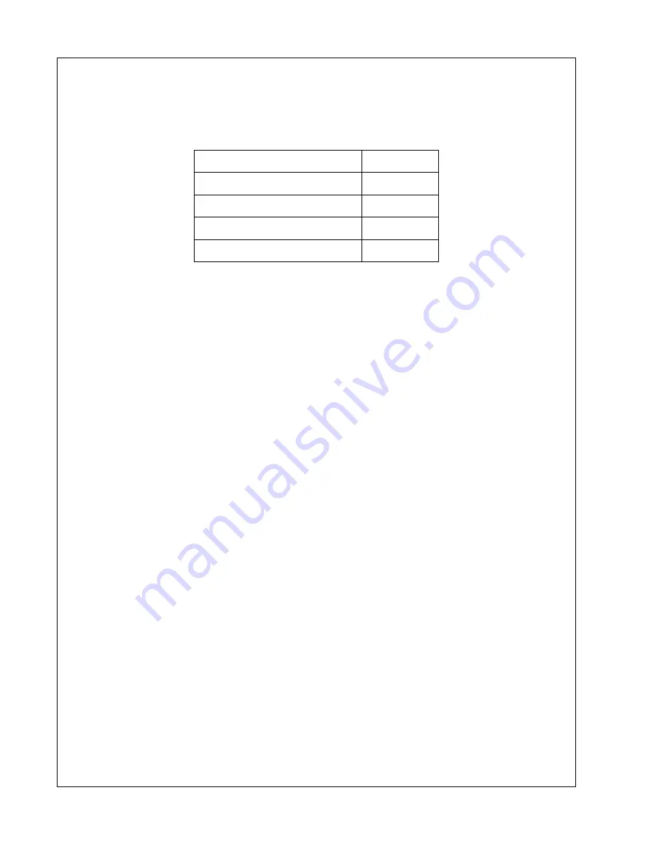
Chlorides

<40 mg/L

Sulfates

<100 mg/L

Total Dissolved Solids

<340 mg/L

Total Hardness

<170 mg/L

pH

5.5 to 9.0

Summary of Contents for 10/125

Page 1: ...501 Sanford Ave Mocksville N C 27028 Book 22442594 1 07 Doosan purchased Bobcat Company from Ingersoll Rand Company in 2007 Any reference to Ingersoll Rand Company or use of trademarks service marks l...

Page 2: ...that consistently meet the requirements of our customers and each other CALIFORNIA Proposition 65 Warning Diesel engine exhaust and some of its constituents are known to the State of California to cau...

Page 3: ...ecords and mail form to 18 Engine Registration 18 DECALS 21 Decals 22 Graphic Form and Meaning of ISO Symbols 22 NOISE EMISSION 29 Noise Emission 30 Compressor Noise Emission Control Information 30 No...

Page 4: ...ting Instructions 52 Prior to Starting 52 Control Panel 54 Diagnostic Auto Shutdown Standard 54 Controls Standard 54 Optional Controls 55 Wedge Diagnostic Display Panel 56 Wedge Diagnostic Display Cod...

Page 5: ...Wear 76 Checking Tensioner Spring Tension 76 Checking Engine Electrical Ground Connections 77 Replenishing Supplemental Coolant Additives SCAs Between Coolant Changes 77 Replacing Fan and Alternator B...

Page 6: ...stem 104 Battery 104 Pressure System 104 Tyres Tyre Tire Pressure 104 Running Gear Wheels 104 Lubrication 105 Engine Lubricating Oil 105 Engine Lubricating Oil Specification 105 Engine Oil Filter Elem...

Page 7: ...Dual Pressure 129 Safety 129 Operating instructions 129 Commisioning 129 Starting and Use 129 Options IQ System 130 Safety 130 Operating Instructions 131 Maintenance 132 Daily maintenance 132 Weekly...

Page 8: ...8 TABLE OF CONTENTS Operating Maintenance Manual TITLE PAGE...

Page 9: ...22442594 9 Foreword...

Page 10: ...specification for USA Canada is adopted and tailored to the territory All components accessories pipes and connectors added to the compressed air system should be of good quality procured from a reput...

Page 11: ...oved by Ingersoll Rand b May impair the safety of users and other persons and c May prejudice any claims made against Ingersoll Rand Table 1 Use of the machine to produce compressed air for a direct h...

Page 12: ...nglish version COPYRIGHT 2003 INGERSOLL RAND COMPANY Generator Use of the generator to supply load s greater than those specified Use of unsafe or unserviceable electrical equipment connected to the g...

Page 13: ...22442594 13 Warranty...

Page 14: ...nditions are met The original airend is retumed assembled and unopened Continued use of genuine Ingersoll Rand parts fluids oils and filters Maintenance is performed at prescribed intervals D Genset G...

Page 15: ...hase at the time of exercising warranty The above warranty does not apply to failures occurring as a re sult of abuse misuse negligent repairs corrosion erosion and normal wear and tear alterations or...

Page 16: ...d Coverage 12 unlimited Available at dealer CUMMINS 24 2000 Major components 3 yrs 10 000 hrs Available at dealer JOHN DEERE in compressors 24 2000 5 yrs 5000 hrs using OEM fluids and filters with 250...

Page 17: ...limited to defects in major components rotors housings gears and bearings and is automatically available when the following conditions are met 1 The original airend is returned assembled and unopened...

Page 18: ...on keep a copy for your records and mail form to Ingersoll Rand Company P O Box 868 Mocksville North Carolina 27028 Attn Warranty Department NOTE Completion of this form validates the warranty Engine...

Page 19: ..._____________ State __________________ State __________________ Zip code_______________ Zip code _______________ Zip code _______________ Telephone______________ Telephone______________ Telephone_____...

Page 20: ...eviewed and understood by the owner user 3 In the event that this unit is to be used within a nuclear facility the owner user shall notify Ingersoll Rand of such use so that Ingersoll Rand may arrange...

Page 21: ...22442594 21 Decals...

Page 22: ...se signs on machines manufactured in Europe which point out potential hazards to the safety of you and others Read and understand thoroughly Heed warnings and follow instructions If you do not underst...

Page 23: ...Decals Operating Maintenance Manual 22442594 23...

Page 24: ...Operating Maintenance Manual Decals 24 22442594...

Page 25: ...Decals Operating Maintenance Manual 22442594 25...

Page 26: ...your DANGER WARNING CAUTION NOTICE Indicates the presence of a hazard which WILL cause serious injury death or property damage if ignored Indicates the presence of a hazard which CAN cause serious inj...

Page 27: ...Decals Operating Maintenance Manual 22442594 27...

Page 28: ...Operating Maintenance Manual Decals 28 22442594...

Page 29: ...22442594 29 Noise Emission...

Page 30: ...e acts included in the prohibition against tampering are these 1 Removal or rendering inoperative any of the following a the engine exhaust system or parts thereof b the air intake system or parts the...

Page 31: ...rves the right to make changes or add improvements without notice and without incurring any obligation to make such changes or add such improvements to products sold previously The Purchaser is urged...

Page 32: ...purchaser that this air compressor was designed built and equipped to conform at the time of sale to the first retail purchaser with all applicable U S EPA Noise Control Regulations This warranty is n...

Page 33: ...and correct the leak s B Safety and Control Systems Repair or replace all safety and control systems or circuits as malfunction occurs No compressor should be operated with either system bypassed dis...

Page 34: ...hould be inspected after each 100 hours of operation for loose damaged or deteriorated components Repairs or replacements should be made before the next period of use G Cooling Systems All components...

Page 35: ...ting Maintenance Manual 22442594 35 MAINTENANCE RECORD FOR NOISE EMISSION CONTROL AND EXTENDED WARRANTY ITEM NO DESCRIPTION OF WORK OR COMMENTS HOUR METER READING MAINT INSPECT DATE LOCATION CITY STAT...

Page 36: ...Operating Maintenance Manual Noise Emission 36 22442594...

Page 37: ...22442594 37 Safety...

Page 38: ...tenance Manuals Make sure that all protective covers are in place and that the canopy doors are closed during operation The specification of this machine is such that the machine is not suitable for u...

Page 39: ...and that the machine cannot be started accidentally Ensure that the machine is operating at the rated pressure and that the rated pressure is known to all relevant personnel All air pressure equipment...

Page 40: ...s injury or death Always attach a safety flow restrictor to each hose at the source of supply or branch line in accordance with OSHA Regulation 29CFR Section 1926 302 b Never allow the unit to sit sto...

Page 41: ...ich may require proper disposal when performing maintenance and service tasks Contact local authorities for proper disposal of these materials Battery A battery contains sulphuric acid and can give of...

Page 42: ...orrect selection and adjustment of the vehicle towing hitch and on variable height running gear adjustment of the drawbar Make sure wheels tyres and tow bar connectors are in safe operating condition...

Page 43: ...22442594 43 General Arrangement...

Page 44: ...anel access door Fuel fill B Package air inlet Engine oil filter C Access items Fuel filter Separator element fill Engine and compressor air filter Compressor oil filter E Access items Fuel filters Ra...

Page 45: ...Access items G Track width Separator element fill H Variable height drawbar Compressor oil filter 184 29 4681 minimum 189 21 4806 Fuel filters maximum Dipstick J Variable height drawbar Engine oil fil...

Page 46: ...3 bar 150 PSI Normal operating discharge pressure 14 115 VHP400WIR 14 bar 200 PSI Maximum allowable pressure 7 170 P600WIR 8 6 bar 125 PSI Maximum allowable pressure 10 125 HP450WIR 12 1 bar 175 PSI...

Page 47: ...with Pro Tec because the resulting mixture could cause damage to the airend In the event that Pro Tec is not available and or the end user needs to use an approved single grade engine oil the complet...

Page 48: ...obtained by request through Ingersoll Rand customer services department P600WIR 7 170 HP450WIR 10 125 VHP400WIR 14 115 Type model Ingersoll Rand Number of cylinders 6 Oil capacity 22 1 litres 5 75 GA...

Page 49: ...he correct fork lift truck slots or marked lifting tie down points are used whenever the machine is lifted or transported When selecting the working position of the machine ensure that there is suffic...

Page 50: ...plant effective check valves and isolation valves must be fitted and controlled by work procedures so that one machine cannot accidently be pressurized over pressurised by another WARNING If flexible...

Page 51: ...22442594 51 Operating Instructions...

Page 52: ...he unit has to be operated out of level it is important to keep the engine oil level near the high level mark with the unit level CAUTION Do not overfill either the engine or the compressor with oil 2...

Page 53: ...rvice valve s to ensure that all pressure is relieved from the system Close the service valve s 7 CAUTION Do not operate the machine with the canopy doors in the open position as this may cause overhe...

Page 54: ...n See Wedge diagnostic panel for more detail 3 Hourmeter Records running time for maintenance 4 Compressor Discharge Pressure Gauge Indicates pressure in receiver tank psi kPa 5 Fuel Level Gauge Indic...

Page 55: ...Air Temp Gauge Indicates in F and C Normal operating range 185 F 85 C to 248 F 120 C 10 Engine Oil Pressure Gauge Indicates engine oil pressure psi kPa 11 Engine Water Temp Gauge Indicates coolant tem...

Page 56: ...Oil Pressure Fault indicator lamp Indicates shutdown due to low engine oil pressure 4 Restricted Air Filter Alarm indicator lamp Indicates engine compressor air inlet filters need service 5 High Engi...

Page 57: ...pressor or engine fault Refer to manual for list of codes and service requirements Wedge Diagnostic Display Codes Alert Shutdown Condition Code Light Blinks Code Light Steady Delay sec Engine Speed 90...

Page 58: ...CAN Bus Problem 71 CPRSR Malf Alert Shutdown Condition Code Light Blinks Code Light Steady Delay sec Dedicated Lights Low Fuel Level Fuel Level Fuel Level 3 Air Filter Restriction Option Soiled Filter...

Page 59: ...Voltage High 4 Engine Oil Pressure Input Voltage Low 18 Engine Oil Pressure Moderately Low 105 3 Manifold Air Temperature Input Voltage High 4 Manifold Air Temperature Input Voltage Low 16 Manifold Ai...

Page 60: ...Derate Switch Active 1076 0 Pump Control Valve Closure Too Long 1 Pump Control Valve Closure Too Short 5 Pump Solenoid Circuit Open 6 Pump Solenoid Circuit Severely Shorted 7 Pump Control Valve Closu...

Page 61: ...the service valve open and air is flowing from the valve Wait to Start Lamp Turn the key switch to position 1 until the Wait To Start Lamp 14 extinguishes Turn the key switch to crank position 3 engi...

Page 62: ...ines which operate in excess of 7 bar 100 psi can optionally be fitted with a dual pressure switch inside the unit This switch selects between 7 bar 100 psi and the machine rated pressure cfm remains...

Page 63: ...Should any of the safety shut down conditions occur the unit will stop Refer to the Wedge diagnostic display codes table for a listing of shutdown conditions CAUTION To ensure an adequate flow of oil...

Page 64: ...Operating Maintenance Manual Operating Instructions 64 22442594...

Page 65: ...22442594 65 Engine Instructions...

Page 66: ...mber greater than 50 is preferred especially for temperatures below 20 C 4 F or elevations above 1500 m 5000 ft Cold Filter Plugging Point CFPP below the expected low temperature OR Cloud Point at lea...

Page 67: ...in the combustion chamber Handling and Storing Bio Diesel Fuel WARNING Handle fuel carefully Do not fill the fuel tank when engine is running DO NOT smoke while you fill the fuel tank or service the...

Page 68: ...g periods of time If fuel is stored for more than a month prior to use or there is a slow turnover in fuel tank or supply tank add a fuel conditioner to stabilize the fuel prevent water condensation M...

Page 69: ...e interval by 50 Diesel fuel with sulfur content greater than 1 0 10 000 ppm is not recommended Diesel Engine Coolant The engine cooling system is filled to provide year round protection against corro...

Page 70: ...endation for use of supplemental coolant additives The use of non recommended supplemental coolant additives may result in additive drop out and gelation of the coolant Add the manufacturer s recommen...

Page 71: ...water is used as the coolant even when coolant conditioners are added Drain cooling system and refill with recommended glycol base engine coolant as soon as possible Engine Break In Service The engine...

Page 72: ...0 05 is used the oil and filter change interval is also reduced Item Lubrication and Maintenance Service Intervals Check Engine Oil and Coolant Level Daily 500 Hours 12 months 2000 Hours 24 months As...

Page 73: ...ilters or bowls if equipped two or three turns b Loosen air bleed plug B two full turns on fuel filter mounting and drain water from bottom until fuel starts to drain out c When fuel starts to drain o...

Page 74: ...termine the correct oil fill quantity for your engine see ENGINE CRANKCASE OIL FILL QUANTITIES in the Specifications Section of this manual IMPORTANT Immediately after completing any oil change crank...

Page 75: ...p the retaining ring and rotate it counterclockwise turn Remove ring with filter element 6 Inspect filter mounting base for cleanliness Clean as required NOTE Raised locators on fuel filter canisters...

Page 76: ...on swing arm is hitting the fixed stop check mounting brackets alternator belt tensioner idler pulley etc and the belt length Replace belt as needed Checking Tensioner Spring Tension A belt tension g...

Page 77: ...ial in your cooling system to protect against rust liner pitting and corrosion and freeze ups due to incorrect coolant dilution CAUTION DO NOT mix one brand of SCA with a different brand Recharge the...

Page 78: ...ines with Electronic Fuel Systems and Stanadyne DE10 Pump CAUTION Escaping fluid under pressure can penetrate the skin causing serious injury Avoid hazards by relieving pressure before disconnecting h...

Page 79: ...on Retighten connection to specifications 3 Repeat procedure for remaining injection nozzles if necessary until all air has been removed from fuel system If engine still will not start see your author...

Page 80: ...things first Double check before beginning the disassembly Determine cause and make a thorough repair After making repairs operate the engine under normal conditions to verify that the problem and cau...

Page 81: ...Improper type of fuel Consult fuel supplier use proper type fuel for operating conditions Water dirt or air in fuel system Drain flush fill and bleed system Clogged fuel filter Replace filter element...

Page 82: ...n pump out of time See your authorized servicing dealer Electronic fuel system problem See your authorized servicing dealer Turbocharger not functioning Turbocharger engines only See your authorized s...

Page 83: ...or loose connections or leaks Faulty radiator cap Have technician check Stretched poly vee belt or defective belt tensioner Check automatic belt tensioner and check belts for stretching Replace as req...

Page 84: ...arge Loose or corroded connections Clean and tighten connections Sulfated or worn out batteries See your authorized servicing dealer Stretched poly vee belt or defective belt tensioner Adjust belt ten...

Page 85: ...oking for wires that have pulled out of connectors poorly positioned terminals damaged connectors and corroded or damaged splices and terminals Look for broken wires damaged splices and wire to wire s...

Page 86: ...e for Long Term Storage The following storage preparations are good for long term engine storage up to one year After that the engine should be started warmed up and retreated for an extended storage...

Page 87: ...at you may not be familiar with 1 Remove all protective coverings from engine Unseal all openings in engine and remove covering from electrical systems 2 Remove the batteries from storage Install batt...

Page 88: ...cking 0 31 0 38 mm 0 012 0 015 in Exhaust Checking 0 41 0 48 mm 0 016 0 019 in Intake Adjusting 0 36 mm 0 014 in Exhaust Adjusting 0 46 mm 0 018 in Max Crank Pressure 0 5 kPa 2 H2O Vibration Damper Ma...

Page 89: ...spaces provided For a complete listing of all items to be performed and the service intervals required see chart earlier in this manual Emission System Warranty U S EPA Emissions Control Warranty Sta...

Page 90: ...equipment The presence of an emissions labels signifies that the engine has been certified with the EPA and or CARB The EPA and CARB warranties only apply to new engines having the certification labe...

Page 91: ...22442594 91 Maintenance...

Page 92: ...amps C Air Cleaner Service Indicators C Fuel Tank Fill at end of day C Oil Leaks C Fuel Leaks C Drain Water From Fuel Filters D Coolant Leaks C Radiator Filler Cap C Air Cleaner Precleaner Dumps C Fan...

Page 93: ...nal legislation C Check adjust clean or replace as necessary CBT Check before towing CR Check and report D Drain G Grease R Replace T Test W I or when indicated if earlier Refer to specific sections o...

Page 94: ...Fuel Water Separator Element R Compressor Oil Filter Element R Compressor Oil R Engine Oil Change R Water Pump Grease R Wheels Bearings Seals etc C Engine Coolant C R Fuel Filter Element R Injection N...

Page 95: ...before towing CR Check and report D Drain G Grease R Replace T Test W I or when indicated if earlier Refer to specific sections of the operator s manual for more information Lights running brake turn...

Page 96: ...CR Check and report D Drain G Grease R Replace T Test W I or when indicated if earlier Refer to specific sections of the operator s manual for more information Initial500 miles 850 km Daily Weekly Mon...

Page 97: ...l protective equipment should be worn Ensure that maintenance personnel are adequately trained competent and have read the Maintenance Manuals Prior to attempting any maintenance work ensure that all...

Page 98: ...and guards extreme temperatures inflow and outflow of air intermittently moving parts safety valve discharge etc appropriate personal protective equipment is worn loose clothing jewellery long hair et...

Page 99: ...he discharge air Compressor Oil Filter Refer to the MAINTENANCE CHART in this section for the recommended servicing intervals Removal WARNING Do not remove the filter s without first making sure that...

Page 100: ...at the air and oil filter elements are correctly maintained If however the element has to be replaced then proceed as follows Removal WARNING Do not remove the filter s without first making sure that...

Page 101: ...e before the machine is put back into service Compressor Oil Cooler and Engine Radiator When grease oil and dirt accumulate on the exterior surfaces of the oil cooler and radiator the efficiency is im...

Page 102: ...wed to become more than half full Removal CAUTION Never remove and replace element s when the machine is running Clean the exterior of the filter housing and remove the filter element by releasing the...

Page 103: ...up after the machine is shut down or at the end of each working day At six month intervals drain any sediment or condensate that may have accumulated in the tank s Fuel Filter Water Separator The fue...

Page 104: ...ing clamp should be kept tight enough to prevent the battery from moving Pressure System At 500 hour intervals it is necessary to inspect the external surfaces of the system from the airend through to...

Page 105: ...t into service If for any reason the unit has been drained it must be re filled with new oil before it is put into operation Engine Lubricating Oil The engine oil should be changed at the engine manuf...

Page 106: ...iping and oil cooler by removing the drain plug s and collecting the used oil in a suitable container Replace the drain plug s ensuring that each one is secure NOTE If the oil is drained immediately a...

Page 107: ...he machine Refer to STARTING INSTRUCTIONS in the OPERATING INSTRUCTIONS section of this manual Adjust the service valve on the outside of the machine to maintain rated pressure at full speed If full s...

Page 108: ...Operating Maintenance Manual Maintenance 108 22442594...

Page 109: ...Maintenance Operating Maintenance Manual 22442594 109...

Page 110: ...ded warranty Compressor oil carryover oil consumption may be greater with the use of alternative fluids Design Operating Pressure Ambient Temperature Specification 100 psi to 300 psi 10 F to 125 F 23...

Page 111: ...or s manual warranty section for details or contact your I R representative Ingersoll Rand Preferred Fluids 1 gal 3 8 Litre 5 gal 19 0 Litre 55 gal 208 2 Litre 220 gal 836 Litre Preferred IR Pro TecTM...

Page 112: ...Operating Maintenance Manual Maintenance 112 22442594...

Page 113: ...22442594 113 Machine Systems...

Page 114: ...T2 Pressure transducer regulation system 0 100 PSIG ECON Engine controller PM Plug machine ID IG Isochronous governor R3 Idle sel J50 G2 Wait to start lamp RS Relay spst J50 K3 Inlet heater RT1 Thermi...

Page 115: ...Spare P56 Oil pressure SW2 Display scroll POUT1 Engine key switch SW3 Low fuel shutdown POUT2 Solenoid start run SW4 Switch service air POUT3 Comp fault lamp SW5 Air filter rest option POUT4 Engine fa...

Page 116: ...Operating Maintenance Manual Machine Systems 116 22442594 Harness System Schematic J1939 CAN Communications Schematic...

Page 117: ...22442594 117 Service Tools...

Page 118: ...llow Used to repair Deutsch connectors HDT 48 00 Deutsch Terminal Crimp Tool Used to crimp Deutsch connector terminals DD Deutsch Terminal Crimping Tool Used to crimp Deutsch connector terminals 54729...

Page 119: ...e from electrical and electronic parts distributors 54729660 Weather Pack Terminal Removal Tool 54699632 Deutsch Terminal Removal Tool Blue 54699640 Deutsch Terminal Removal Tool Red 54699624 Deutsch...

Page 120: ...DA Service Tool 54699616 Deutsch Terminal Removal Tool 22073886 Packard Crimp Tool 22073878 Thermistor Simulator 54749635 Connector Repair Kit 54699657 Deutsch Terminal Removal Tool 54749643 Packard M...

Page 121: ...500 psi PRESSURE TRANSDUSER 1 22173579 WEDGE CONTROLLER 1 36898922 THERMISTOR PROBE 2 22199061 W1 CHASSIS HARNESS 1 36840841 SOELNOID VALVE 1 22179659 W1 CHASSIS HARNESS DIAGRAM N A 36853521 STARTER...

Page 122: ...Operating Maintenance Manual Service Tools 122 22442594...

Page 123: ...22442594 123 Fault Finding...

Page 124: ...Refer to MAINTENANCE SECTION Safety shut down system in operation Check the safety shut down switches Engine starts but stalls when the switch returns to position I Electrical fault Test the electric...

Page 125: ...Premature unloading Check the regulation system Excessive vibration Engine speed too low See Engine speed too low Leaking oil seal Improperly fitted oil seal Replace the oil seal Refer also to the En...

Page 126: ...PEED AND PRESSURE REGULATION ADJUSTMENT in the MAINTENANCE section of this manual Loose pipe hose connections Check all pipe hose connections Faulty safety valve Check the relieving pressure Replace t...

Page 127: ...22442594 127 Options...

Page 128: ...machine is stopped and the system has been completely relieved of all air pressure Refer to STOPPING THE UNIT in the OPERATING INSTRUCTIONS section of this manual CAUTION If the nylon tubes to the lu...

Page 129: ...th at least the higher rated pressure Operating instructions Commisioning Check that switch and solenoid are functioning correctly Switch handle up Lower pressure selected Switch handle right Higher p...

Page 130: ...d engine life and reduced airend life CAUTION Excessively restricted filter elements may cause an increase in the amount of aerosol water and oil carryover which could result in damage to downstream e...

Page 131: ...rate at temperatures less that 2 C 35 F unless equipped with low ambient IQ option Operating Instructions Starting and use Select desired air type using diverter valve and start machine normally Using...

Page 132: ...ndicators for the filters are mounted on the filter heads If so equipped an automatic restriction indicator located behind the filters will shut down the compressor if restriction exceeds recommended...

Page 133: ...2004 Ingersoll Rand Company Printed in the USA...

Reviews: