


SMT-BD2
3.3
–
X1
CONNECTOR FOR ABSOLUTE SINGLE TURN
S
IN
/C
OS ENCODER CONFIGURATION
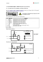
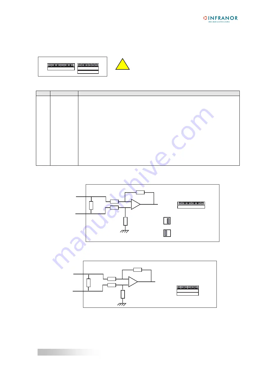
The “ Absolute single turn Sin/Cos encoder ” configuration (Heidenhain ERN 1085 or compatible) is selected
according to the following COM and COD jumpers setting (
see chapter 5, section 1: Hardware adjustments
).
COD
B5
B4
B2
B1
COM
B3
!
A wrong jumper configuration may damage the
encoder and amplifier electronics.
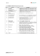
The corresponding X1 connector pin function description is given below.
PIN
FUNCTION
REMARKS
1
Reference R/ Differential input of the Sin/Cos encoder reference pulse R/
9
Reference R
Differential input of the Sin/Cos encoder reference pulse R
2
Channel A/
Differential input of the Sin/Cos encoder channel A/
10
Channel A
Differential input of the Sin/Cos encoder channel A
3
Channel B/
Differential input of the Sin/Cos encoder channel B/
11
Channel B
Differential input of the Sin/Cos encoder channel B
6
Channel C/
Differential input of the Sin/Cos encoder channel C/
14
Channel C
Differential input of the Sin/Cos encoder channel C
8
Channel D/
Differential input of the Sin/Cos encoder channel D/
7
Channel D
Differential input of the Sin/Cos encoder channel D
5
+5V
Sin/Cos encoder supply voltage (400 mA max. current)
4
GND
Sin/Cos encoder supply GND
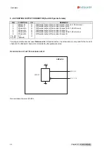
12
TC
Motor thermal sensor input (10 mA max. load current)
13
GND
Motor thermal sensor GND
15 reserved
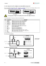
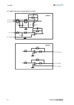
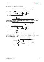
Specification of the Sin/Cos encoder channels
X1-9, 10, 11
X1-1, 2, 3
SMT-BD2
10 K
Ω
10 K
Ω
-
+
100 K
Ω
100 K
Ω
120
Ω
B2
B1
ZM
ZM
COD
COD jumpers configuration
Marker pulse enabled
Marker pulse disabled
ZM jumper configuration
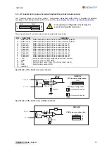
Specification of the Sin/Cos commutation channels
X1-14, 7
X1-6, 8
SMT-BD2
10 K
Ω
10 K
Ω
-
+
50 K
Ω
50 K
Ω
1 K
Ω
B5
B4
COM
B3
COM jumpers configuration
19
Chapter 3 - Inputs - Outputs


