Option "c" · Chapter 5: Adjustable parameters
13
CHAPTER 5 - ADJUSTABLE PARAMETERS
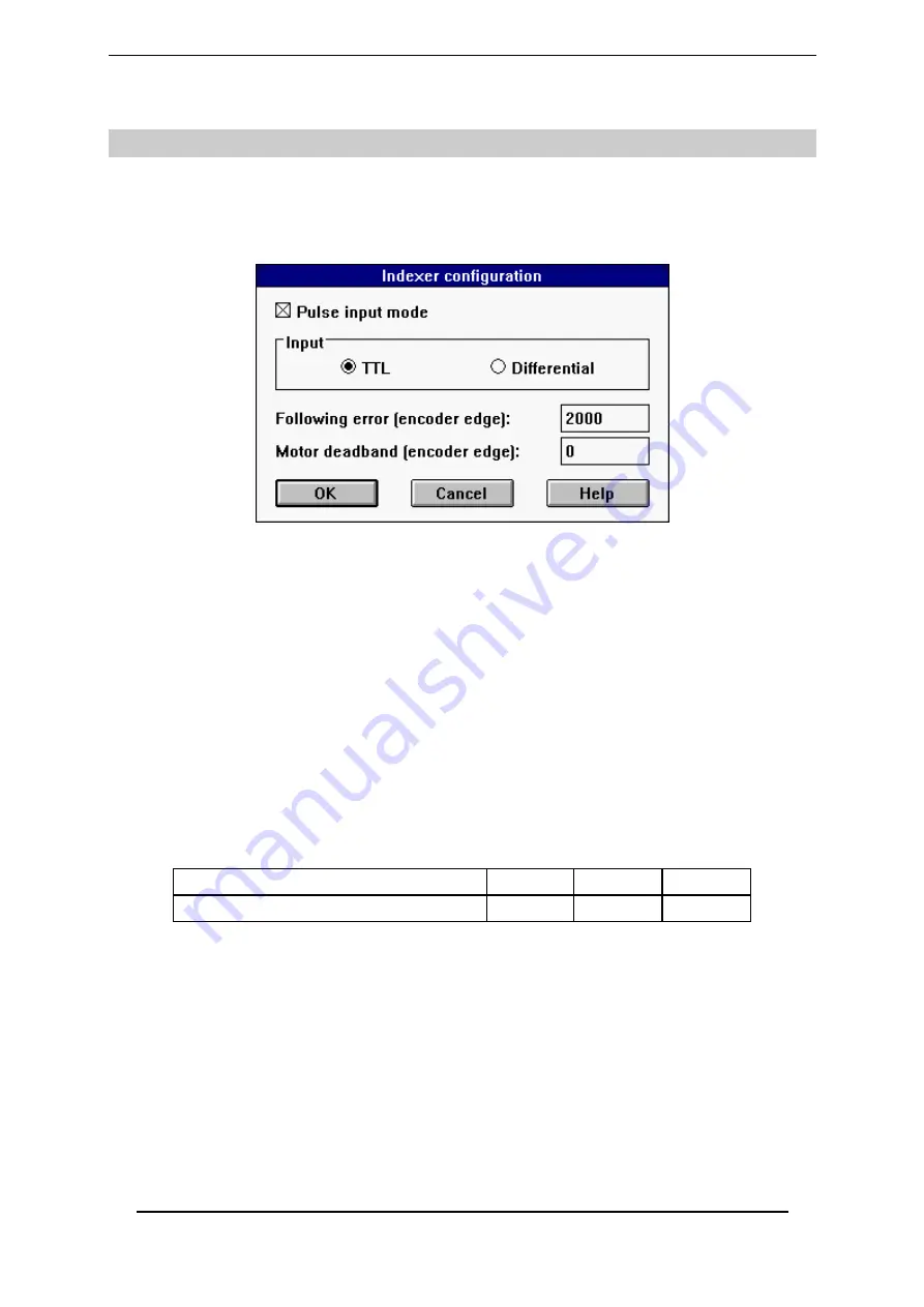
The parameters used for positioning in stepping motor emulation are accessible via
the Indexer
/ Electronic Gearbox
submenu of the
Advanced functions
menu, in the
BPCW
software.
1 - OPERATION MODE
The operation in stepping motor emulation is selected by the
Pulse input mode
function in the
Indexer / Electronic Gearbox
menu of the
Advanced functions
menu.
This mode corresponds to the motor position control with a PIV + feedforward regulator. The
position input command emitted by the indexer board is received as an incremental input
command on the X2 connector.
2 - APPLICATION PARAMETERS
The
Encoder resolution
parameter is accessible in the
ENCODER RESOLUTION
module of the
adjustment panel in the
BPCW
software. It defines the number of encoder pulses for one
revolution of the motor shaft. The limit value of this parameter according to the maximum motor
speed (
Maximum speed
) is indicated in the chart below:
MAXIMUM SPEED (rpm)
900
3 600
14 000
MAXIMUM ENCODER RESOLUTION
8192
4096
1024
The following parameters are accessible via the
Indexer / Electronic Gearbox
submenu of the
Advanced functions
menu.
The
Following error
parameter defines the maximum permissible value of the position error.
When the position error reaches half of this value, the
POS
output is disabled and the following
error fault (
Position
error) is blinking on the amplifier front panel. When the position error
reaches the value defined by the
Following error
parameter, the following error fault (
Position
error) is released and the amplifier is disabled. This parameter is expressed as motor steps (motor
resolution encoder pulses x 4). The adjustment range is between 0 and 32 767 steps.
The
Motor deadband
parameter defines a tolerance range of the position input command,
where the position loop is open. This parameter is expressed as motor steps (motor resolution
encoder pulses x 4). The adjustment range is between 0 and 32 767 steps.


