background image

Option "c"  ·  Chapter 3: Inputs - Outputs

10

1.3 - I

NDEXER INPUT SPECIFICATION

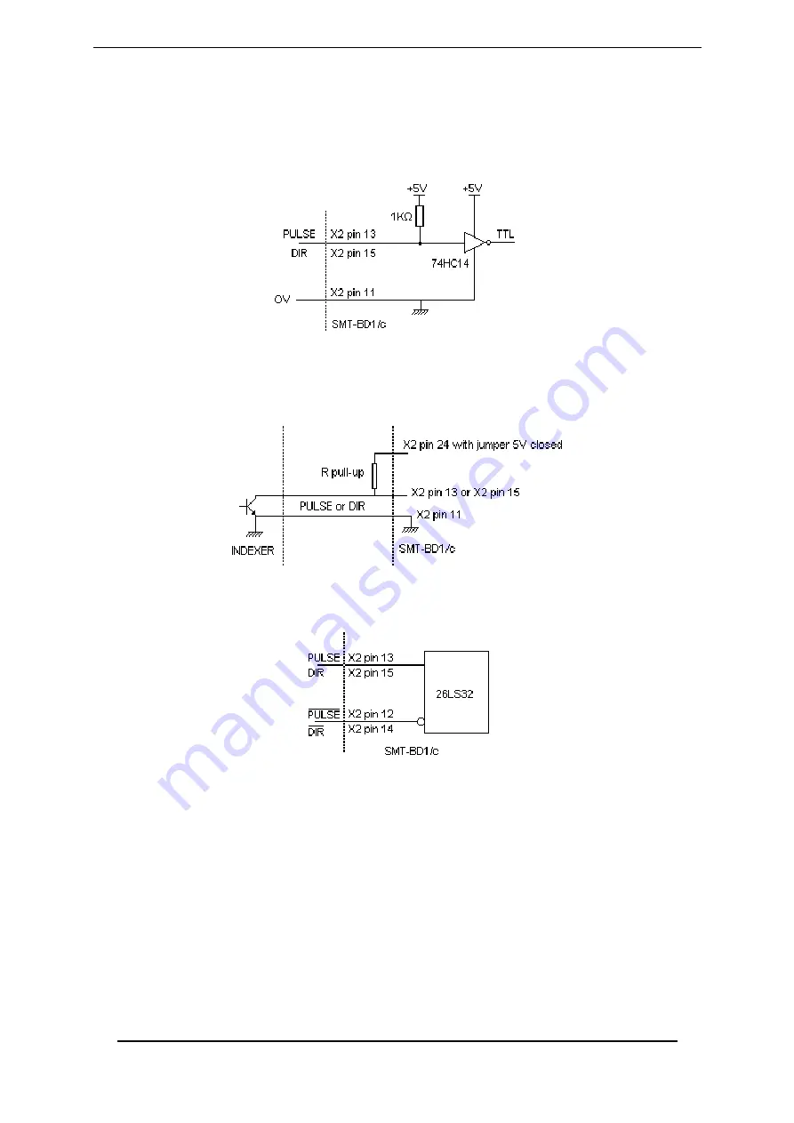
The TTL 

PULSE

 and 

DIR

 inputs are connected to the amplifier as shown below:

For indexers with open collector output and operating at high frequencies (>  100  kHz), a pull-up
resistor corresponding to the transistor output current must be wired in the X2 connector, as
shown below (the pull-up resistor is parallel mounted to the 1 k

W

 resistor in the amplifier).

The differential 

PULSE

 and 

DIR

 inputs are connected to the amplifier as shown below:

This type of input is suitable for long indexer-amplifier connections (a 26LS31 driver is
recommended).

Summary of Contents for SMT-BD1 Series

Page 1: ...id if the items are installed according to the recommendations of the racks and amplifiers manuals Any contact with electrical parts even after power down may involve physical damage Wait for 30 seconds after power down before handling the rack or the amplifiers residual voltage INFRANOR does not assume any responsibility for any physical or material damage due to improper handling or wrong descri...

Page 2: ...2 ...

Page 3: ...3 Option c POSITIONING IN STEPPING MOTOR EMULATION WITH SMT BD1 c AMPLIFIER ...

Page 4: ...l indexer signals 12 2 WIRING RECOMMENDATIONS 12 CHAPTER 5 ADJUSTABLE PARAMETERS 13 1 OPERATION MODE 13 2 APPLICATION PARAMETERS 13 3 POSITION REGULATOR PARAMETERS 14 CHAPTER 6 COMMISSIONING 15 1 CHECKING THE CONFIGURATION 15 2 POWERING 15 3 START AND ADJUSTMENT 15 CHAPTER 7 FAULT FINDING 17 1 POSITION FAULT 17 2 OPERATING PROBLEMS 17 2 1 Loud crackling noise in the motor at standstill 17 2 2 Loud...

Page 5: ...t motions without motor jerking without saturation in the amplifier and without important overshoot the board MUST generate acceleration deceleration ramps during the motion trapezoidal shape The maximum output pulse train frequency of the board limits at the same time the motor maximum speed and the position resolution according to the formula below Max PULSE signal frequency pps Max motor speed ...

Page 6: ...pr up to 3 600 rpm Max 1 024 ppr up to 14 000 rpm Drive position repetability 1 step Drive position accuracy 8 Arc mins 1 step in standard 2 Arc mins 1 step on special request Position regulator PIV Feedforward Sample period 0 5 ms Integrator antisaturation system Antiresonance filter Adjustable digital gains Position loop bandwidth Cut off frequency for 45 phase shift Selectable 50 Hz 75 Hz or 10...

Page 7: ...TOR Resolver Ref SIN COS T mot GT Resolver conversion Resolver oscillator Encoder output CA CB CZ AOK CV Analog input Analog input ILIM fc fc CV0 CI Enable RESET CV GT Ramp fdc Speed loop d dt Vector control Current loops EEPROM Serial interface Current monitor Pmes Imes ID IQ PWM Protections T mot Enable Logic supplies ENABLE AOK ERROR SYS ON Power fault Enable DC BUS fc fc CV0 Vref Vmes IDC Sele...

Page 8: ...T The stored fault can be cancelled by the RESET function of the BPCW software by the fault RESET input pin 13 of X4 by turning off the amplifier supply PROTECTION DISPLAY CODE LED Position following error Position l l l R l LED is unlit R LED is lit ...

Page 9: ... POS O Logic output POS position following OK 23 0 V POS O 0 V POS output 10 0 V GND 11 0 V I Indexer 0 V input 13 PULSE I Indexer PULSE signal input Chapter 3 1 3 12 PULSE I Indexer PULSE signal input Chapter 3 1 3 15 DIR I Indexer DIR signal input Chapter 3 1 3 14 DIR I Indexer DIR signal input Chapter 3 1 3 16 17 18 19 Reserved Reserved 9 Reserved Reserved 20 21 22 Reserved Reserved 24 25 Reser...

Page 10: ...high frequencies 100 kHz a pull up resistor corresponding to the transistor output current must be wired in the X2 connector as shown below the pull up resistor is parallel mounted to the 1 kW resistor in the amplifier The differential PULSE and DIR inputs are connected to the amplifier as shown below This type of input is suitable for long indexer amplifier connections a 26LS31 driver is recommen...

Page 11: ... bits linearity 2 IDC Imon ID IQ Vref Vmon Pos err 3 Speed input command CV 10 V for maximum speed 4 Speed signal GT 8 V for 14 000 rpm 5 DAC 2 output 10 V resolution 8 bits linearity 2 IDC Imon ID IQ Vref Vmon Pos err See BPCW Options manual part Digital oscilloscope Linearity 10 on logic board types 01612A 01612B and 01612C ...

Page 12: ...als Pulse and Direction of the indexer amplifier connection use a cable with a 360 shield connection via the metal plated connectors at both cable ends see standard manual of the SMT BD1 digital amplifier chapter 8 part 6 and connect the 0 Volt of both indexer and amplifier pin GND on the X2 connector Be careful about the polarity between indexer and amplifier for the TTL signals Pulse and Directi...

Page 13: ... parameter according to the maximum motor speed Maximum speed is indicated in the chart below MAXIMUM SPEED rpm 900 3 600 14 000 MAXIMUM ENCODER RESOLUTION 8192 4096 1024 The following parameters are accessible via the Indexer Electronic Gearbox submenu of the Advanced functions menu The Following error parameter defines the maximum permissible value of the position error When the position error r...

Page 14: ...e Indexer Electronic Gearbox control is described below The Controller parameters function in the Advanced functions menu of the BPCW software allows the access to all regulator parameters The Speed error low pass filter parameter defines the cut off frequency a 3 db Fev of the 1st order filter acting upon the speed error The value of this parameter depends on the selected bandwidth The Proportion...

Page 15: ...ng the antiresonance filter Filter Antiresonance The antiresonance filter is accessible from the BPCW software version 2 6 and the amplifier EPROM version 5 7 Execute the MODIFY function in the ENCODER RESOLUTION module and select the Encoder resolution parameter see Chapter 2 part 1 for the limitation of this parameter according to the motor maximum speed The position resolution on the motor shaf...

Page 16: ...ental to the following error but it has no influence on the motor position regulation at standstill shaft stiffness Adjust the following error threshold Following error at its minimum value in order to avoid a triggering during a rotation at maximum speed Check for the shaft stiffness at standstill If necessary it is possible to get a higher stiffness by increasing at first the speed loop gain by ...

Page 17: ...put command answers the requirements in Chapter 4 2 2 LOUD NOISE IN THE MOTOR AT STANDSTILL AND WHEN RUNNING Check for the rigidity of the mechanical coupling between motor and load backlashes and elasticities in the gearboxes and couplings Execute the AUTO TUNING function again by selecting a lower bandwidth Medium or Low If the problem remains renew the AUTO TUNING procedure by activating the an...

Page 18: ...Option c Chapter 8 Appendix 18 CHAPTER 8 APPENDIX LOCATION DIAGRAM OF THE HARDWARE OPTIONS ...

Reviews: