background image

Dual-Lens People Counting Camera

·

Quick Start Guide


12 


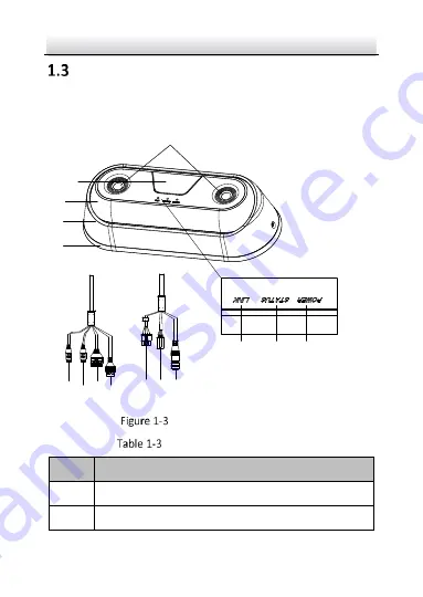
Type III Camera for Mobile Scenario 

This camera type has different cable groups for different models. The 
following figure shows both cable groups. 

1

2

3
4

5

6

7

8

9 10 11

12131415


Overview of Type III Camera 


Description of Type III Camera 

No. 

Description 

IR 

Lens 

Summary of Contents for ILK-IDPC

Page 1: ...0 Dual Lens People Counting Camera Quick Start Guide ...

Page 2: ...ARDING TO THE PRODUCT WITH INTERNET ACCESS THE USE OF PRODUCT SHALL BE WHOLLY AT YOUR OWN RISKS OUR COMPANY SHALL NOT TAKE ANY RESPONSIBILITES FOR ABNORMAL OPERATION PRIVACY LEAKAGE OR OTHER DAMAGES RESULTING FROM CYBER ATTACK HACKER ATTACK VIRUS INSPECTION OR OTHER INTERNET SECURITY RISKS HOWEVER OUR COMPANY WILL PROVIDE TIMELY TECHNICAL SUPPORT IF REQUIRED SURVEILLANCE LAWS VARY BY JURISDICTION ...

Page 3: ...owever there is no guarantee that interference will not occur in a particular installation If this equipment does cause harmful interference to radio or television reception which can be determined by turning the equipment off and on the user is encouraged to try to correct the interference by one or more of the following measures Reorient or relocate the receiving antenna Increase the separation ...

Page 4: ...purchase of equivalent new equipment or dispose of it at designated collection points For more information see www recyclethis info 2006 66 EC battery directive This product contains a battery that cannot be disposed of as unsorted municipal waste in the European Union See the product documentation for specific battery information The battery is marked with this symbol which may include lettering ...

Page 5: ...ted Warnings Proper configuration of all passwords and other security settings is the responsibility of the installer and or end user In the use of the product you must be in strict compliance with the electrical safety regulations of the nation and region Please refer to technical specifications for detailed information Input voltage should meet both the SELV Safety Extra Low Voltage and the Limi...

Page 6: ...t the service center Cautions Make sure the power supply voltage is correct before using the camera Do not drop the camera or subject it to physical shock Do not touch sensor modules with fingers If cleaning is necessary use clean cloth with a bit of ethanol and wipe it gently If the camera will not be used for an extended period please replace the lens cap to protect the sensor from dirt Do not a...

Page 7: ... electrolytic capacitor of the equipment shall be replaced regularly according to their average enduring time The average time varies because of differences between operating environment and using history so regular checking is recommended for all the users Please contact with your dealer for more details Improper use or replacement of the battery may result in hazard of explosion Replace with the...

Page 8: ...io 10 Type III Camera for Mobile Scenario 12 2 Installation 15 Type I Camera Installation 15 Type II Camera Installation 20 Type III Camera Installation 25 3 Setting the Network Camera over the LAN 31 Wiring 31 Activating the Camera 32 Activation via Web Browser 32 Activation via IDM Software 33 Modifying the IP Address 35 4 Accessing via Web Browser 37 0504061070605 ...

Page 9: ...ting camera for indoor outdoor and mobile scenarios Attention Disassembling the camera without professional technical instruction may affect the accuracy of people counting function Contact the technical support for repair if any malfunction happens Type I Camera for Indoor Scenario 1 1 2 3 4 5 6 7 Overview of Type I Camera ...

Page 10: ...or Solid blue running properly Flashing red network connection abnormal Flashing blue other exceptions 4 Power supply interface 12 VDC 5 RS 485 and alarm I O interface 6 Network interface support power over Ethernet 7 Reset button Note Press RESET for about 10s when the camera is powering on or rebooting to restore the default settings including the user name password IP address port No etc ...

Page 11: ...ens People Counting Camera Quick Start Guide 10 Type II Camera for Outdoor Scenario 1 2 3 4 5 6 7 8 9 10 11 12 Overview of Type II Camera Description of Type II Camera No Description 1 IR 2 Lens 3 Camera body ...

Page 12: ...Ethernet interface 10 Link indicator Flashing yellow normal network communication Off no network communication 11 Status indicator Solid green working properly Off when the people counting function is in the following conditions 1 off 2 abnormal shutdown 3 abnormal heartbeat 12 Power indicator Solid red working properly Off power supply abnormal ...

Page 13: ... III Camera for Mobile Scenario This camera type has different cable groups for different models The following figure shows both cable groups 1 2 3 4 5 6 7 8 9 10 11 12131415 Overview of Type III Camera Description of Type III Camera No Description 1 IR 2 Lens ...

Page 14: ...work communication 7 Status indicator Solid green working properly Off when the people counting function is in the following conditions 1 off 2 abnormal shutdown 3 abnormal heartbeat 8 Power indicator Solid red working properly Off power supply abnormal 9 Alarm I O RS 485 10 Power cord 12 VDC 11 M12 aviation plug 12 RS 485 13 Power cord 12 VDC 14 Alarm I O 15 RJ45 Ethernet interface ...

Page 15: ...a has one cable group The relation between RJ45 wire and M12 wire is shown in the following figure and table 1 2 3 4 1 8 M12 Aviation Plug RJ45 Network Interface Figure 1 4 RJ45 Interface and M12 Aviation Plug Wire Relation M12 Wire RJ45 Wire TX 1 1 TX 3 2 RX 2 3 RX 4 6 ...

Page 16: ...e all the related equipment is power off during the installation Check the specification of the products for the installation environment Make sure that the ceiling is strong enough to withstand four times the weight of the camera and the bracket Type I Camera Installation Steps Select a suitable mounting position The relations among focal length for the focal length of your camera see the label o...

Page 17: ...Dual Lens People Counting Camera Quick Start Guide 16 Installation Recommendation ...

Page 18: ...g Height Ground Max Detection Span Focal Length mm Mounting Height m Max Detection Span m 2 0 2 5 1 8 2 0 3 0 2 9 2 0 3 5 4 0 2 0 4 0 5 2 2 8 3 0 2 2 2 8 3 5 3 1 2 8 4 0 4 0 2 8 4 5 4 8 2 8 4 7 5 2 4 0 4 0 2 8 4 0 4 5 3 4 4 0 5 0 4 0 4 0 5 5 4 6 4 0 6 0 5 2 Notes ...

Page 19: ...surface parallel to the ground or the optical axes of both lenses should be perpendicular to the ground It is recommended to install the camera at an entrance exit where the detection area can be covered better Paste the drill template to the desired mounting place 123 8 2 Φ4 5 Drill Template Align the Front mark on drill template with that on mounting base Fix the mounting base with supplied scre...

Page 20: ...ide 19 Fix the Mounting Base Align the Front mark on the mounting base with that on camera bottom Fit the hooks on mounting base in the big end of the slots on camera bottom Push to get the camera clasped Hook Hook Slot Slot Clasp Install the Camera ...

Page 21: ...Camera Installation Steps Select a suitable mounting position The relations among focal length for the focal length of your camera see the label on camera body mounting height and maximum detection span are shown in the following table Installation Recommendation ...

Page 22: ...ight Ground Max Detection Span Focal Length mm Mounting Height m Max Detection Span m 2 8 3 0 2 2 2 8 3 5 3 1 2 8 4 0 4 0 2 8 4 5 4 8 2 8 4 7 5 2 4 0 4 0 2 8 4 0 4 5 3 4 Focal Length mm Mounting Height m Max Detection Span m 4 0 5 0 4 0 4 0 5 5 4 6 4 0 6 0 5 2 Notes ...

Page 23: ...o install the camera at an entrance exit where the detection area can be covered better Paste the drill template Note Pay attention to The Lens mark on the template which stands for the direction at which the camera lens can be adjusted Cable Hole Drill Template of Type II Camera Drill screw holes if you use expansion screws and plan cable routing ...

Page 24: ...ra on a cement surface use expansion screws If you route the cable through the ceiling cut a cable hole in advance Loosen the screws and remove the enclosure of the camera Remove the Enclosure Attach the silicone pad to the mounting base of the camera Route the cable and screw the camera and the silicone pad to the mounting place with 4 supplied screws ...

Page 25: ... Guide 24 Silicone Pad Mounting Base Fix the Camera Adjust tilting position of the lens 1 Loosen screw 1 and screw 2 Screw 1 Screw 2 Tilt 0 to 45 Adjust Tilting Position 2 Adjust the tilting position to make the lens directly face the ground Note ...

Page 26: ...he lens panel should parallel to the ground or the optical axes of both lenses should be perpendicular to the ground 3 Tighten the two screws Install the enclosure back and tighten the screws Install the Enclosure Back Type III Camera Installation Steps Select a suitable mounting position ...

Page 27: ...Height m Max Detection Span m 2 0 2 3 1 3 2 0 2 5 1 8 2 0 3 0 2 9 Notes The camera should be installed at 2 1 to 3 0 meters height above the first step of the entry exit area of the vehicle if several steps are available It is recommended to install the camera at an entrance exit where the detection area can be covered better Paste the drill template Note ...

Page 28: ...on at which the camera lens can be adjusted Drill Template of Type III Camera Drill screw holes if expansion screws are used and cable hole according to the drill template Loosen the screws and remove the enclosure of the camera Enclosure Remove the Enclosure Attach the shock absorbing pad to the mounting base of the camera Note ...

Page 29: ...camera on a flat surface use the silicone pad If you install the camera on a curved surface use the EVA pad EVA Pad Silicone Pad Shock Absorbing Pad Attach Shock Absorbing Pad Route the cable and screw the camera and the shock absorbing pad to the mounting place with 4 supplied screws Fix the Camera Adjust tilting position of the lens ...

Page 30: ...make the lens directly face the ground Note To get better counting accuracy the lens panel should parallel to the ground or the optical axes of both lenses should be perpendicular to the ground 3 Tighten the two screws Screw 1 Screw 2 Tilt 0 to 45 Adjust Tilt Position Install the enclosure back and tighten the screws ...

Page 31: ...Dual Lens People Counting Camera Quick Start Guide 30 Install the Enclosure Back ...

Page 32: ... any network attacks and information leakage please strengthen your own protection If the product does not work properly please contact with your dealer or the nearest service center Wiring Connect to the camera to the network according to the following figures 半球 Network Cable or Network Camera Computer Connecting Directly 网络交换机 半球 Network Cable Network Cable or or Network Camera Computer Connect...

Page 33: ...s examples to introduce the camera activation Please refer to the User Manual of Network Camera for Activation via Client Software Activation via Web Browser Steps 1 Power on the camera and connect the camera to the network 2 Input the IP address into the address bar of the web browser and click Enter to enter the activation interface Notes The default IP address of the camera is 192 168 1 64 The ...

Page 34: ...case letters lower case letters numbers and special characters in order to increase the security of your product And we recommend you reset your password regularly especially in the high security system resetting the password monthly or weekly can better protect your product 4 Confirm the password 5 Click OK to save the password and enter the live view interface Activation via IDM Software IDM sof...

Page 35: ...Camera for other two activation methods Steps 1 Run the IDM software to search the online devices 2 Check the device status from the device list and select the inactive device Select inactive device Input and confirm password IDM Interface Note The IDM software supports activating the camera in batch Please refer to the user manual of IDM software for details 3 Create a password and input the pass...

Page 36: ...ate to start activation You can check whether the activation is completed on the popup window If activation failed please make sure that the password meets the requirement and try again Modifying the IP Address Purpose To view and configure the camera via LAN Local Area Network you need to connect the network camera in the same subnet with your PC Use the IDM software or client software to search ...

Page 37: ...t with your computer by either modifying the IP address manually or checking Enable DHCP Modify the IP Address 4 Input the admin password and click Modify to activate your IP address modification The batch IP address modification is supported by the IDM please refer to the User Manual of IDM for details ...

Page 38: ...ove version Steps 1 Open the web browser 2 In the browser address bar input the IP address of the network camera and press the Enter key to enter the login interface Note The default IP address is 192 168 1 64 If the camera is not activated please activate the camera first according to Section 3 2 3 Input the user name and password The admin user should configure the device accounts and user opera...

Page 39: ...in before viewing the live video and managing the camera Please follow the installation prompts to install the plug in Note Close the web browser to finish the installation of the plug in Download Plug in 6 Reopen the web browser after the installation of the plug in and repeat steps 2 to 4 to login Note ...

Page 40: ...Dual Lens People Counting Camera Quick Start Guide 1 For detailed instructions of further configuration please refer to the User Manual of Network Camera ...

Page 41: ...0 COPYRIGHT 2018 EFB Elektronik GmbH EFB Elektronik GmbH Striegauer Straße 1 33719 Bielefeld Germany www infralan security de ...

Reviews: