85
INFOSEC UPS SYSTEM
–
15, rue du Moulin
–
44880 Sautron
–
France
–
www.infosec-ups.com
hotline : +33 (0)2 40 76 15 82
–
fax : +33(0)2 40 94 29 51
–
–
07 19 AA 59 205 03
2. Add one new unit into the parallel system
1) You cannot add one new unit into the parallel system when whole system is running. You must cut
off the load and shutdown the system.
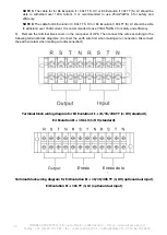
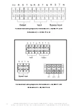
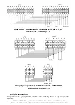
2) Make sure all of the UPS are the parallel models, and follow the wiring refer to section 2-4.
3) Install the new parallel system refers to the previous section.
3. Remove one unit from the parallel system
There are two methods to remove one unit from the parallel system:
First method:
4) Press the “OFF” key twice and each time should be lasted for more than 0.5s. Then, the UPS will
enter into bypass mode or no output mode without output.
5) Turn off the external output breaker of this unit, and then turn off the input breaker of this unit.
6) After it shuts down, you can turn off the battery breaker (for long-run model) and remove the
parallel and share current cables. And then remove the unit from the parallel system.
Second method:
6) If the bypass is abnormal, you can not remove the UPS without interruption. You must cut off the
load and shut down the system first.
7) Make sure the bypass setting is enabled in each UPS and then turn off the running system. All
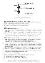
UPSs will transfer to Bypass mode. Remove all the maintenance bypass covers and set the
maintenance switches from “UPS” to “BPS”. Turn off all the input breakers and battery breakers in
parallel system.
8) Turn off the output breaker and remove the parallel cable and share current cable of the UPS which
you want to remove. Then, remove it from parallel system.
9) Turn on the input breaker of the remaining UPS and the system will transfer to Bypass mode.
Set
the maintenance switches from “BPS” to “UPS and put the maintenance bypass covers back.
10) Turn on the remaining UPS according to the previous section.
Warning:
(Only for the parallel system)
●
Before turning on the parallel system to activate inverter, make sure that all unit’s maintenance
switch at the same position.
●
When parallel system is turned on to work through inverter, please do not operate the maintenance
switch of any unit.
●
If applying for parallel system, ECO mode is not supported. Therefore, please DO NOT “enable”
ECO mode in any unit.
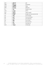
3-6. Meaning of the abbreviations on the LCD Display
Abbreviation
Display content
Meaning
ENA
Enable
DIS
Disable
ATO
Auto
BAT
Battery
NCF
Normal mode (not CVCF mode)
CF
CVCF mode (frequency converter mode)
SUB
Subtract
ADD
Add
ON
On


