background image

2-14

Chapter 2: Hardware installation

Checking the power status

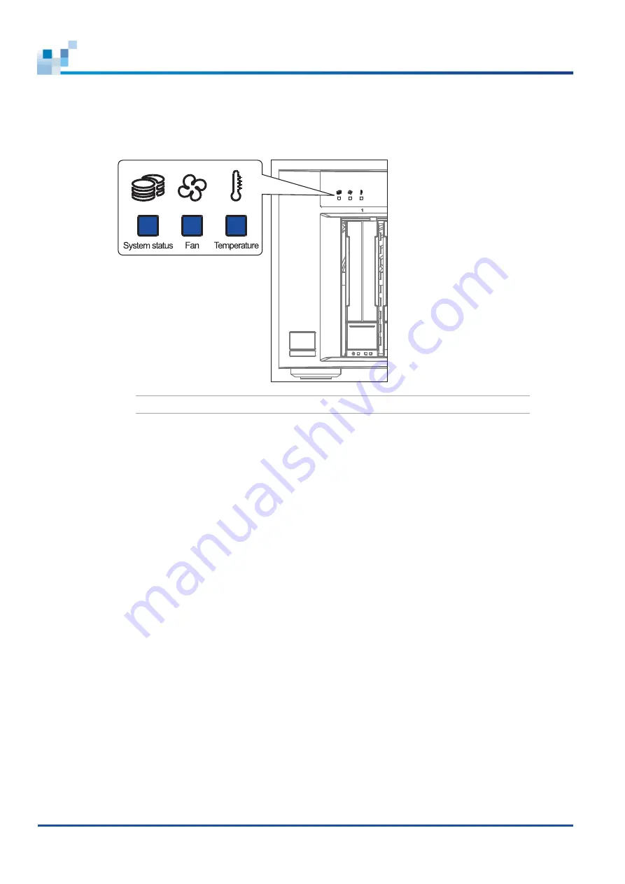
Once the system is on, no LEDs should light up in red or amber, nor should you hear an alarm from the 

system. Start verifying the system status via the front panel LEDs.

NOTE:

  Refer to chapter 

System maintenance

 for more information regarding the LED description.

2.3.5  Turning off the system

To turn off the system, press the power button for 5 seconds. When the system beeps and the HDD 

LEDs flash, the system is initiating to shut down.

To forced shut down the system, press the power button longer, approximately 10 seconds. 

Summary of Contents for EonStor GSe Pro 200

Page 1: ...EonStor GSe Pro 200 Series Hardware Manual...

Page 2: ...d sales representative or technical support for assistance To the extent permitted by applicable laws Infortrend shall NOT be responsible for any interoperability or compatibility issues that may aris...

Page 3: ...2 2 Installation procedures 2 2 2 2 1 Unpacking the system 2 2 2 2 2 Preparing the installation 2 2 2 2 3 Installing the hard drives 2 3 2 2 4 Installing the host board 2 8 2 3 Connections 2 10 2 3 1...

Page 4: ...iv Appendices Certifications A 1 User warning A 1 Declaration of the presence condition of the restricted substance marking A 2 Contact information A 3...

Page 5: ...abinet Do not leave drive bays empty as it will affect airflow efficiency Secure each enclosure module using its retention screws Place power cords and other cables away from foot traffic Do not place...

Page 6: ...rtrend certified components e g SFP SFP HBA card iSCSI cable FC cable memory module etc ESD precautions Handle the modules by their retention screws ejector levers or the module s metal frame faceplat...

Page 7: ...Version Date Description 1 0 June 2017 Initial release 1 1 December 2017 Modified section Rear Panel and Restore default setting 1 2 November 2018 Modified section 2 3 4 Power connection Fixed bugs in...

Page 8: ...x USB 3 1 Gen2 2 x USB 3 0 Drive interface 6 Gb s SATA Maximum number of drives GSe Pro 205 System 5 Expansion 32 GSe Pro 208 System 8 Expansion 32 Expansion enclosure supported model JB Pro 208 Driv...

Page 9: ...tiers Advanced snapshot 256 per volume 4096 per system Advanced block level local replication Replication pairs per source volume 8 Replication pairs per system 256 Advanced block level local replicat...

Page 10: ...y by region Power Power supply 1 x 250 W AC voltage 100 VAC 3 5A 240 VAC 3 5A with PFC auto switching Frequency 47 63 Hz Environment Temperature Operating 0 C 40 C without BBU CBM 0 C 35 C with BBU CB...

Page 11: ...dimension order is W x H x D Notification Various event notification methods including email and SNMP trap Network configuration IPv6 support Fixed or dynamic address Dual Gigabit Ethernet with Jumbo...

Page 12: ...contents and quantity may vary depending on the system model and order requests System package Accessories box Unpacking list and China RoHS compliance documentation Enclosure chassis Quick installati...

Page 13: ...ives in a tower form factor Each drive is configurable to RAID 0 5 and 6 offering you high performance and data backup functionalities This series is a perfect NAS storage solution for small scale to...

Page 14: ...ssis are designed to allow installation to the rack or a cabinet 1 2 1 Front panel Number Part Description 11 Drive trays Each drive tray is hot swappable and holds a 2 5 inch or 3 5 inch hard drive 1...

Page 15: ...security devices 11 10 GbE ports SFP These ports support 8 Gbps Fibre Channel 10 Gigabit Ethernet with data rates of up to 16 Gbps 11 1 GbE ports RJ 45 These 8 pin ports support a standard Ethernet ca...

Page 16: ...art Description 11 DIMM slots Each slot accommodates 2 DDR4 memory modules 11 Flash module This module serves as a cache backup and also contains NAS OS WARNING DO NOT remove the flash module If you w...

Page 17: ...LED name Description 11 System status This LED provides the status when the system 11 Fan This LED provides the status of the system s fan 11 Temperature status LED This LED provides the system s tem...

Page 18: ...mber Part Description 11 Release button Push this button to unlock the drive tray from the drive tray slot 11 Power status LED This LED provides the power status of the disk drive 11 Drive busy LED Th...

Page 19: ...r panel that allows you to connect to GSe Pro 200 system and a series of JB 208 systems Number Part 11 Power socket 11 Kensington lock 11 SAS expansion port status LEDs 11 Rotary ID switch 11 SAS expa...

Page 20: ...be available before the system installation Memory modules If you want to change the pre installed DIMM modules ensure that they are compatible and purchased from a qualified vendor Contact your vend...

Page 21: ...led with in your package Accessory box contents This box contains the following DB9 to USB cable Screws Compliance and technical documentations Support CD EonOne Management software and manual firmwar...

Page 22: ...rd drives that have the same capacity and rotation speeds RPM This storage uses the least common denominator approach which means that the maximum capacity used in each drive to create a RAID array is...

Page 23: ...stallation may damage the hard drives Handle the disk drives with extreme care and observe all ESD prevention procedures when installing the hard drives ONLY use the screws that are bundled in the sys...

Page 24: ...s without data loss 11 2 No fault tolerance 1 drive failed and data loss occured 11 2 1 mirrored pair 11 3 1 11 4 2 IMPORTANT Knowing the location of your drives is vital There is a risk of data loss...

Page 25: ...ard drive s screw holes to the tray s assigned screw holes with the interface connectors facing the open side of the tray and the label is facing up A then secure the drive with four screws bundled wi...

Page 26: ...tem has all the drive bays occupied with the drive trays even if there are no hard drives installed Without the drive trays the ventilation is compromised and may cause overheating 4 When the tray is...

Page 27: ...ys install the host board in slot 1 if you only need to install one NOTE When adding or replacing a host board the firmware automatically restores the system to its default settings To install a host...

Page 28: ...2 9 EonStor GSe Pro 200 Series Hardware Manual 3 Tighten the thumb screws built with the host board to secure it in place NOTE Keep the dummy covers in a cool dry place...

Page 29: ...embling your LAN 2 3 2 Connecting the devices to a network For initial setup connect your GSe Pro system to a PC via an Ethernet cable and launch its interface via a browser to configure the settings...

Page 30: ...ust be handled with care DO NOT bend or twist the cables when connecting the systems installed to the rack Setting the expansion IDs Each expansion system must have a unique ID and you can configure t...

Page 31: ...he list below and check the following 1 The hard drives are correctly installed to the drive trays 2 All drive trays are installed to the system whether or not they contain a hard drive 3 The system i...

Page 32: ...networking devices 2 Turn on the JBOD expansion systems 3 Press the power button on the front panel 4 Turn on the application servers NOTES The NAS server operates using DHCP Dynamic Host Configurati...

Page 33: ...system status via the front panel LEDs NOTE Refer to chapter System maintenance for more information regarding the LED description 2 3 5 Turning off the system To turn off the system press the power...

Page 34: ...via the serial port For more details see the firmware manual in the bundled CD EonOne EonOne is a browser based GUI graphic user interface software that you can install into a local or remote computer...

Page 35: ...Description 11 System The system is ready The system is booting up or shutting down The device encounters critical error s OFF The system is off 11 Fan The system fan s is are running normally A fan...

Page 36: ...e message you must check the drive tray LEDs to find the correct location of the failed drive Number LED name Color Description 11 Power status The drive bay is occupied and working normally Disk driv...

Page 37: ...s established Data I O is ongoing OFF No connection is established 11 Speed 10 Gb connection is established 1 Gb connection is established OFF No connection is established When you restore the system...

Page 38: ...Manual 10 GbE SFP port LEDs Number LED name Color Status Description 11 Link A connection is established Data I O is ongoing OFF No connection is established 11 Speed 10 Gb connection is established O...

Page 39: ...ment on hand Doing so may disrupt the internal airflow Consult with the qualified engineers who are familiar with the system to recommend you of the component replacements DO NOT use excessive force w...

Page 40: ...Contact your system vendor to help you purchase the compatible DRAM modules NOTE Refer to section ESD precautions for safety information To replace the memory module 1 Shut down your system Wait for a...

Page 41: ...ware Manual 4 Insert the replacement DIMM carefully into the DIMM socket with the DIMM s notch aligned to the DIMM socket s notch guide 5 Slide back the cover to the system A then secure it with the s...

Page 42: ...the firmware automatically restores the system to its factory settings when adding or replacing a host board To replace the host board 1 Shut down your system Wait for a minute for the remaining elect...

Page 43: ...4 5 EonStor GSe Pro 200 Series Hardware Manual 4 Install the replacement host board to the host board slot 5 Tighten the thumb screws built with the host board to secure it in place...

Page 44: ...avoid touching the circuits and interface connectors To replace the hard drive 1 Identify the faulty hard drive using the EonOne software NOTE See section Hard drive designation for the order of the...

Page 45: ...ur system has all the drive bays occupied with the drive trays even if there are no hard drives installed Without the drive trays the ventilation is compromised and may cause overheating 5 When the tr...

Page 46: ...put activities 2 Save the current configuration using Export NVRAM 3 Turn off the system 4 Insert the paper clip to the Restore Default button then press and hold until the Restore Default LED lights...

Page 47: ...61000 3 3 2013 EN 55024 2010 A1 2015 BSMI CNS 13438 FCC FCC Part 15 subpart B Environment IEC 60068 2 MIL STD 810E 883E ISTA ASTM D3332 IPC TM 650 Others ISO7779 3744 RoHS Microsoft WHQL Windows Serv...

Page 48: ...ower cable Fan 1 0 1 wt 0 01 wt Note 1 Exceeding 0 1 wt and exceeding 0 01 wt indicate that the percentage content of the restricted substance exceeds the reference percentage value of presence condit...

Page 49: ...ation Americas Address 435 Lakeside Dr Sunnyvale CA 94085 USA Telephone 1 408 988 5088 Fax 1 408 988 6288 Email sales us infortrend com Website https www infortrend com us Home Support http support in...

Page 50: ...https www infortrend com uk Home Support http support infortrend com Account Logon Infortrend worldwide sales offices Spain and Portugal sales offices Email sales es infortrend com cs eu infortrend co...

Page 51: ...s www infortrend com pl Home Support http support infortrend com Account Logon Middle East sales offices Email sales meat infortrend com Website https www infortrend com ae Home Support http support i...

Reviews: