


9
INSIGHT DLP
DIRECTOR 2200 Appliance Hardware Installation Guide
www.infolocktech.com
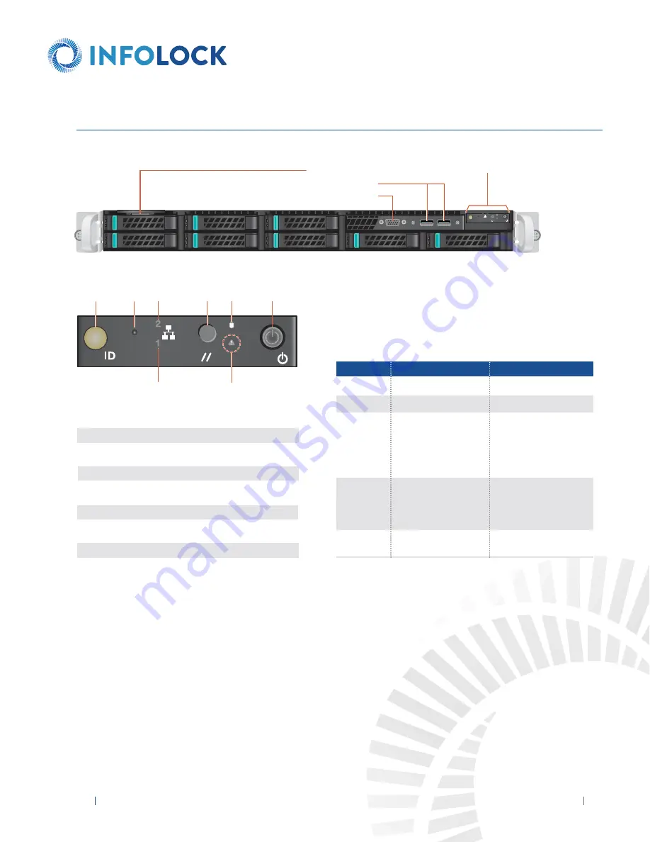
Seriaal Number Slot
USB Ports
Video Port
Fr
4
3
2
1
ID
ront Panel Illustration
See Detail Chart
8. FRONT PANEL OPERATION
A
B C
G
System
Status LED
D E
F
Status LED
Press the Power Button once to power the appliance on.
System ID Button with Integrated LED
NMI Button (recessed, tool required for use)
SPAN Activity LED
System Cold Reset Button
Hard Drive Activity LED
Power Button with Integrated LED
DLP Activity LED
A
B
C
D
E
F
G
System Status LED
There is a bi-color (Green/Amber) LED on the Front Panel (shown on the left).
The LED operation is defined in the following table.
CRITICALITY
Not ready
OK
Degraded - system is
operating in a degraded state
although still functional, OR
system is operating in a
redundant state but with an
impending failure warning
Non-critical - system is
operating in a degraded
state with an impending
failure warning, although
still functioning
Critical, non-recoverable -
system is halted
LED COLOR
OFF
GREEN
GREEN
AMBER
AMBER
SYSTEM STATE
System is not operating
Solid - On
~1 Hz blinking
~1 Hz blinking
Solid - On


