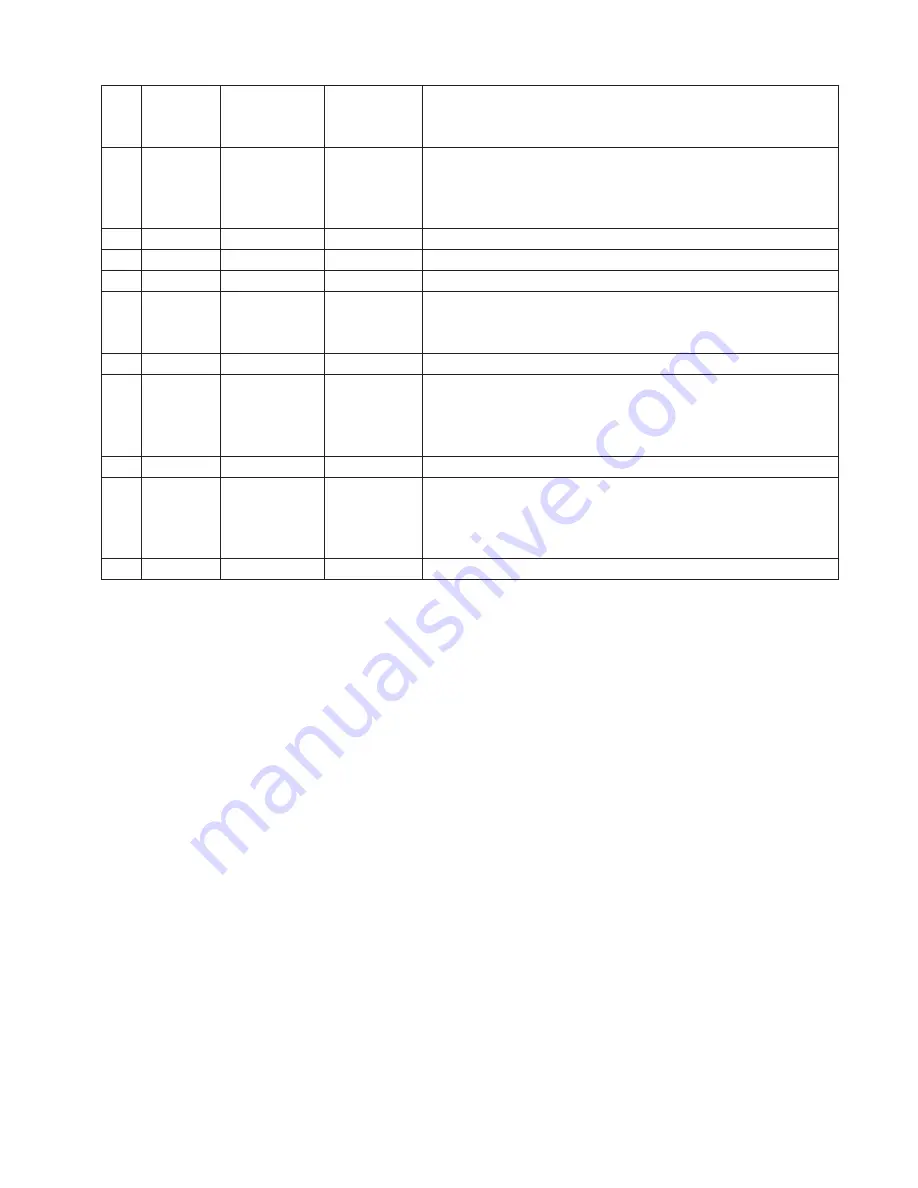
Infinova V3062 Series Installation & Operation Instructions Download Page 13


5

VOIP 

/MON 

Voice Intercom/ 

Auxiliary 

Output 

Function key 

Reserved 

10  

Direction keys 

and 

Confirmation 

Key 

Control key 

The function is the same with the direction keys and 

Ǐ

ENT

ǐ

key on front 

panel 

11 

IRIS 

Iris 

Control key 

Open/Close iris in PTZ control 

12 

FOCUS 

Focus 

Control key 

Increase/Decrease focus in PTZ control 

13 

F1 

F1 

Function key 

Switch monitor 

14 

REC 

Video Record 

Function key 

(1) Switch from the preview interface to the recording management 

interface 

(2) Call up presets in PTZ control, same as 

Ǐ

PRST

ǐ

on front panel 

15 

PLAY 

Play Video 

Function key 

Same as 

Ǐ

PLAY

ǐ

on front panel 

16 

ZOOM 

Zoom in/out 

Control key 

Zoom in/out in PTZ control; 

Note

: Zoom- 

(1) Switch among tabs on submenu 

(2) Hide/Display lower status bar in preview interface 

17 

PTZ 

PTZ 

Control key 

Same as 

Ǐ

PTZ

ǐ

on front panel 

18 PREV 

Multiple-screen Control 

key 

(1) Switch multiple-screen (1, 4 screens) display modes in preview 

interface 

(2) Clear all setting area in "Mask/Video mask alarm/Motion detection" 

setting 

19  

Reserved 


Remote controller installation and use method 

1. Load battery 

(1) Open the cover of the battery cabinet; 
(2) Load 2 No.7 batteries, ensure the polarity is correct; 
(3) Close the battery cabinet. 
 

2. Start using remote controller 

After the DVR has been started up well, press the 

DEV

 key on 

the remote controller, and then input the device number of the 
DVR (the default device No. is 1, it can be modified in "Display"). 
Press 

ENTER

 key, if the indicator on the controller turns green, it 

means that the DVR is connected and can be controlled by remote 
controller. 

Note:

 Device number should be 1 to 127. 


3. Stop using remote controller 

Press 

DEV

 key when the DVR is being controlled, the status 

indicator will turn off, and then the remote controller stops to 
control the DVR. 
 

4. Shutdown DVR via remote controller 

Press Switch key at least 3 seconds to turn off the DVR when it's 
being controlled by controller. 
In the preview mode a login box will pop up if password 
protection is enabled. Users must select the user name and input a 

correct password, and enter to "Shutdown" dialog box to select 
"Confirm" to turn off the DVR. 
 

Note:

Do not turn off the power switch on the rear panel before 

the shutting indicator in front panel turns red. 
In the menu mode, press the power switch key for a few seconds, 
there will be the "shutdown" dialog box if the user has authority 
to operate the "System Management", and then the user can select 
"Confirm" to shutdown the DVR. If the user doesn't have the 
authority on "System Management", the user can not turn off the 
DVR normally.   
 

5. Troubleshooting for remote controller 

If the remote controller doesn't work normally: 

y

Reduce the operating distance between DVR and controller 

y

Aim the controller at the infrared receiver of the DVR 

y

Check the polarity of the battery loaded 

y

Change the used battery and load new battery 

y

Check if the sensor of the controller is obstructed 

y

Check if fluorescence lamp is being nearby 


Note

: Please replace the controller if it doesn't work after the 

above operations. It should be the infrared receiver problem if the 
new controller doesn't work either. Please contact after-sale 
service engineer timely. 

Summary of Contents for V3062 Series

Page 1: ...orders Infinova V3062 Series DVR integrates advanced video compression and storage technologies with 4 ch analog video inputs 4 ch full H 264 video encoding and G711 audio encoding It supports synchronal audio inputs USB2 0 high speed backup and mouse operations The functional DVR can be widely used in security surveillance for small shops band ATMs public security telecommunication traffic and ed...

Page 2: ......

Page 3: ...eo Recorders all comply with Part 15 of the FCC rules Operation is subject to the following two conditions y This device may not cause harmful interference y This device must accept any interference received including interference that may cause undesired operation V3062 series Network Digital Video Recorders have been tested and found to comply with the limits for Class A digital device pursuant ...

Page 4: ... to assure they will be kept away from ground and access way z Refer all service matters to qualified personnel z Save product packaging to ensure availability of proper shipping containers for future transportation Indicates that the un insulated components within the product may carry a voltage harmful to humans Indicates operations that should be conducted in strict compliance with instructions...

Page 5: ...tall the harddisk correctly before use or else you can t make any record operation z The dust of the mainboard may cause short circuit after being damped therefore to maintain a long life usage of the device please clean the mainboard inserts housing and cooling fan regularly z Try not to apply TV set at the local video output interface VIDEO OUT otherwise the output circuit of the DVR VIDEO OUT i...

Page 6: ......

Page 7: ...on DVR 13 4 2 User Login and Authority 13 4 2 1 User Login 13 4 2 2 User Authority 14 4 3 Preview 14 4 3 1 Switch Preview Modes 14 4 3 2 Preview Setting 15 4 4 PTZ Control 15 4 4 1 PTZ Parameters Setting 15 4 4 2 PTZ Control 16 4 4 3 Set and Call Preset 16 4 4 4 Set and Call Pattern 16 4 5 Alarm 16 4 5 1 Channel Alarm 16 4 5 2 Alarm Input 18 4 5 3 Exception Alarm 19 4 6 Alarm Management 19 4 7 Rec...

Page 8: ......

Page 9: ...tern y Support zoom in function by mouse operation when control Infinova second generation domes y Maximum 2 SATA hard disks supported maximum 2TB for each hard disk y Hard disk sleep y The exported file formats are compatible with Windows Hard disk space pre allocation technology is adopted to avoid disk patch y Recording activation mode including manual scheduled alarm triggered y Switch signal ...

Page 10: ...remote controller 2 POWER Power indicator Green indicates the device is running and Red indicates the DVR is powered but not in work grey of indicator represents the power switch on the DVR rear panel is off or the power cord is plugged out 3 Number key Ǐ0ǐ Ǐ9ǐ Input key 1 Input information Ǐ0ǐ Ǐ9ǐ including number capital letters lowercase letters symbols 2 Switch channel in Preview and PTZ contr...

Page 11: ... Control key 1 Zoom out in PTZ Control 2 Switch among tabs in submenu 3 Hide Display lower status bar in preview interface ǏTELEǐ Control key Zoom in in PTZ control ǏPTZǐ Control key 1 Quick enter to PTZ control mode 2 Close iris in PTZ control same as ǏIRIS ǐkey Direction keys Control key 1 Ǐ ǐ Ǐ ǐ keys Select options of right key menu and list box Ǐ ǐ Ǐ ǐ Ǐ ǐ Ǐ ǐkeys Select options in main menu ...

Page 12: ... off the DVR 2 DEV Device Control key Select DVR to be controlled Operation method DEV key Device No ENTER key 3 0 9 Number Key Input key The function is the same with the number keys in front panel 4 EDIT Edit Control key Delete the characters before the cursor 5 A Input Method Control key 1 Switch among input methods numeric English letters and symbol 2 Set the full screen as setting area in Mas...

Page 13: ...that the DVR is connected and can be controlled by remote controller Note Device number should be 1 to 127 3 Stop using remote controller Press DEV key when the DVR is being controlled the status indicator will turn off and then the remote controller stops to control the DVR 4 Shutdown DVR via remote controller Press Switch key at least 3 seconds to turn off the DVR when it s being controlled by c...

Page 14: ...isk 2 SATA hard disk ports are available for V3062 DVR 3 Fix the hard disk on the hard disk rack base 4 Install and fix the rack to DVR with screw 5 Connect the hard disk data cable 6 Connect the hard disk power cord 7 Close and fix the housing with screw Reference Formula to calculate total capacity needed for DVR Calculate total capacity needed by each DVR according to video recording video reco...

Page 15: ...udio input devices e g microphone 6 VIDEO IN Standard BNC interface to connect with analog video device for 4 ch analog video inputs 7 VIDEO OUT Standard BNC interface to connect with monitor for 2 ch analog video outputs VGA OUT1 and OUT2 video outputs are independent from each other in which OUT1 and VGA are for video signal output and menu display and OUT2 for video signal output 8 VGA Standard...

Page 16: ...on As shown in above diagram the internal alarm circuit makes 1 2 output port connected with the corresponding G when there s no alarm And 1 2 output port will contact with 5V node when there s alarm which will activate the indicator or audible alarm There is a jumper J1400 on the mainboard which is closed in factory default setting When open it is used to avoid damage to the device if the externa...

Page 17: ...ntrol line under the leaf spring in the connector and then tighten the screws 3 Place the block pin connector that connected with RS 485 control line to the corresponding green terminal block pin socket Chapter 3 System Menu Introduction Note V3062 series DVR could be operated through front panel USB mouse and remote controller For mouse operation there s no introduction here for it is generally t...

Page 18: ...r as shown in Figure 3 5 Press ǏENTǐ key to confirm the selection Then press Ǐ ǐ Ǐ ǐ Ǐ ǐandǏ ǐkeys to enter the next parameter in the interface 3 1 2 Option Box A 9 in the check box indicates the option is selected Move the cursor to the desired option via Ǐ ǐ Ǐ ǐ Ǐ ǐandǏ ǐ keys then pressǏENTǐ to select it and it cancel the selection if the option is selected when press ǏENTǐkey For example the c...

Page 19: ...or is gray and the buttons will be enabled when there re some other operations conducted or the function is not usable Please contact to manufacturer if need to customize the function 3 1 6 Input Method In the menu operation interface enter the edit status of the editing box a status as shown in Figure 3 6 will appear at the right side then users can input small letter in the editing box by the nu...

Page 20: ...rol Center Alarm Preview and 2 Alarm Outputs Channel Advanced Settings Copy to Preview Monitor Open Close video preview Preview Switching Time Open Close Alarm Preview Alarm Preview Switching Time Preview Mode Alarm Channel Status Alarm Input Alarm Status Video Loss No Alarm Motion Detection Mask Alarm and Input Alarm Status Mark Alarm Input Choice Name Setting Type Schedule Week Time Linkage Reco...

Page 21: ...es with the requirements of the DVR and make sure the DVR is connected with GND correctly Steps 1st Step Connect the power supply on the rear panel 2nd Step Connect the DVR with monitor or display through BNC or VGA interfaces Note Please refer to monitor and VGA display ports in the rear panel diagram in section 2 3 3rd Step Turn on the switch on the rear panel the Switch indicator on the front p...

Page 22: ...ding status list 3 Playback pressǏPLAYǐkey to turn on play interface 4 PTZ control pressǏPTZǐkey to start the PTZ control With the keys combination on the front panel users can enter and switch among different operation interfaces The default menu is preview status In preview status users could live view the image transmitted by front end cameras In the Preview status right click the mouse will op...

Page 23: ...ishing setting and then pressǏENTǐkey to confirm 4 4 PTZ Control Attention Before attempting to perform PTZ control make sure the RS 485 port of the DVR is connected with the RS 485 port of the PTZ system or dome In PTZ control status the below keys could perform the operations as follows Ǐ ǐ Ǐ ǐ Ǐ ǐandǏ ǐkeys Control the movement upward downward leftward and rightward Ǐ0ǐ Ǐ9ǐ keys Switch the chan...

Page 24: ... 2 In the PTZ control status pressǏPRSTǐkey and then input 3 number combination keys to call up the preset For example if want to call up preset 002 after pressǏPRSTǐkey input Ǐ0ǐ Ǐ0ǐ Ǐ2ǐ then the preset 002 is called up 4 4 4 Set and Call Pattern 1 Set pattern The DVR supports maximum 4 patterns only In the interface as shown in Figure 4 5 move the cursor to Pattern and press ǏENTǐkey to enter ed...

Page 25: ...nd save the setting Note In the area setting status pressǏ ǐkey to select all the areas and Ǐ ǐkey to clear all the areas In this system the full screen area is regarded as the mask alarm area regardless its size 3 Set schedule Move the cursor to Schedule option and pressǏENTǐ key to enter Schedule Settings interface as shown in Figure 4 7 Figure 4 7 In the interface move the cursor the white bar ...

Page 26: ...2 Set area of Video mask alarm in section 4 5 1 5 Set schedule Refer to 3 Set schedule of Video mask alarm in section 4 5 1 6 Set alarm linkage Move the cursor to the Linkage option of video motion detection and press ǏENTǐkey to enter the linkage setting interface as shown in Figure 4 9 Figure 4 9 The DVR supports 6 linkage modes as follows y Recording Select the recording channel the DVR will re...

Page 27: ...he setting of audible warning control center and Trigger alarm output Note Different exception alarms may lead to different output linkages See the menu for details 3 Copy and save After finishing setting move the cursor to Copy and press ǏENTǐkey to copy the current parameter setting temporarily then move the cursor to Save button and pressǏENTǐ key to copy the parameters to other channels Exit t...

Page 28: ... higher the manual recording will stop when the channel is in the alarm recording status The manual recording resumes after finishing the alarm recording 2 It s not necessary to restart the manual recording if reboot the DVR 4 7 2 Scheduled Recording Enter the Recording management interface via the main menu Record or ǏRECǐkey on the front panel and press ǏWIDEǐ key to switch to Recording Settings...

Page 29: ...ǏENTǐkey to copy the parameters to other channels Exit the menu without save the copy of parameters is not successful 4 7 3 Alarm Recording From the main menu select Record and enter Recording Settings menu as shown in Figure 4 13 1 Select recording channel Refer to 1 Select recording channel of Scheduled recording in section 4 7 2 2 Set pre recording post recording Refer to 2 Set pre recording po...

Page 30: ...st reverse and frame by frame are only supported by mouse operations Note If there are other operations such as recording performing during playback the actual playing speed cannot reach to the set speed 3 Single channel playback Set the record file search criteria like channel type time range Select and click Search after the setting And press ǏENTǐ button on the panel to confirm the searching Pr...

Page 31: ...tings In the preview interface press ǏMENUǐkey to enter the interface as shown in Figure 5 1 Select Preview and press ǏENTǐkey to enter preview settings interface as shown in Figure 5 2 Press number keyǏ2ǐalso can enter the setting interface as shown in Figure 5 1 Figure 5 1 Figure 5 2 Preview settings include 6 options as follows y Monitor y Video preview y Video preview switch time y Alarm previ...

Page 32: ...NIC y NIC type y IP type y IP address y Subnet mask y Gateway y Mac address y DNS server y Enable DDNS The introduction of each option as follows 1 NIC One NIC available 1 2 NIC type It displays the NIC type of the DVR and is not editable The NIC of the system is 10M 100M 1000M auto adaptive 3 IP type It has 3 options static IP DHCP and PPPoE The operation is the same as the NIC 4 IP address When ...

Page 33: ...ort Settings In the main menu press ǏMENUǐkey to enter the interface as shown in Figure 5 1 Select PTZ COM and press ǏENTǐkey to enter PTZ COM setting interface as shown in Figure 5 6 Press number keyǏ7ǐalso can enter the setting interface in the interface shown in Figure 5 1 Press ǏWIDEǐkey to switch to serial port settings as shown in Figure 5 7 Figure 5 6 Figure 5 7 The settings include 5 optio...

Page 34: ... within 1 to 15 characters The password should be number only with the length within 8 to 15 characters Note The system support maximum 16 users The system will assign network preview network playback local playback and view system log privileges for the new user The administrator can change the privileges of the new user 4 Edit user Select the user to be edited and move the cursor to icon and pre...

Page 35: ... interfaces of prompt box progress bar playback PTZ control login and area setting 9 Enable password protection The system requires to input password when enter to the other interfaces from preview interface if enable the password protection The default is enable password protection 5 5 2 Time Settings In the preview mode press ǏMENUǐkey to enter the interface as shown in Figure 5 1 Select System ...

Page 36: ...o HD option as shown in Figure 5 15 Figure 5 15 If the hard disk needs formatting move the cursor to the checkbox in the row of Formatting and press ǏENTǐkey then press Apply button to start the formatting and confirm the formatting method The process may be slow if it s the first time to format the disk and a prompt box will pop up to indicate the formatting process and don t perform other operat...

Page 37: ...system supports USB mode only Select USB in the list and move the cursor to Browse and press ǏENTǐ key to pop up the dialog box with the updated file list in the U disk It s empty if there s no file Select the file and press Upgrade button to perform the upgrade Press Cancel or ǏESCǐkey to return If no U disk or U disk not insert correctly the system will pop up a confirmation box to require user ...

Page 38: ...cording in the list of Adjust volume for then select on Microphone in the list of Show the following volume controls as shown in the following figure Figure 5 23 5 Click OK to return the recording dialog box shown in the following figure Figure 5 24 6 Adjust the volume of microphone as shown in above figure and the setting of the sound card properties for PC is completed After setting the talk bac...

Page 39: ......

Page 40: ...Infinova 51 Stouts Lane Monmouth Junction NJ 08852 U S A Tel 1 888 685 2002 USA only 1 732 355 9100 Fax 1 732 355 9101 sales infinova com V1 1 1307 ...

Reviews: