24 | ILM-17/19 PA
ILM-17/19 PA | 25
ENG
CONTROLS AND FUNCTIONS
MOUNTING GUIDE
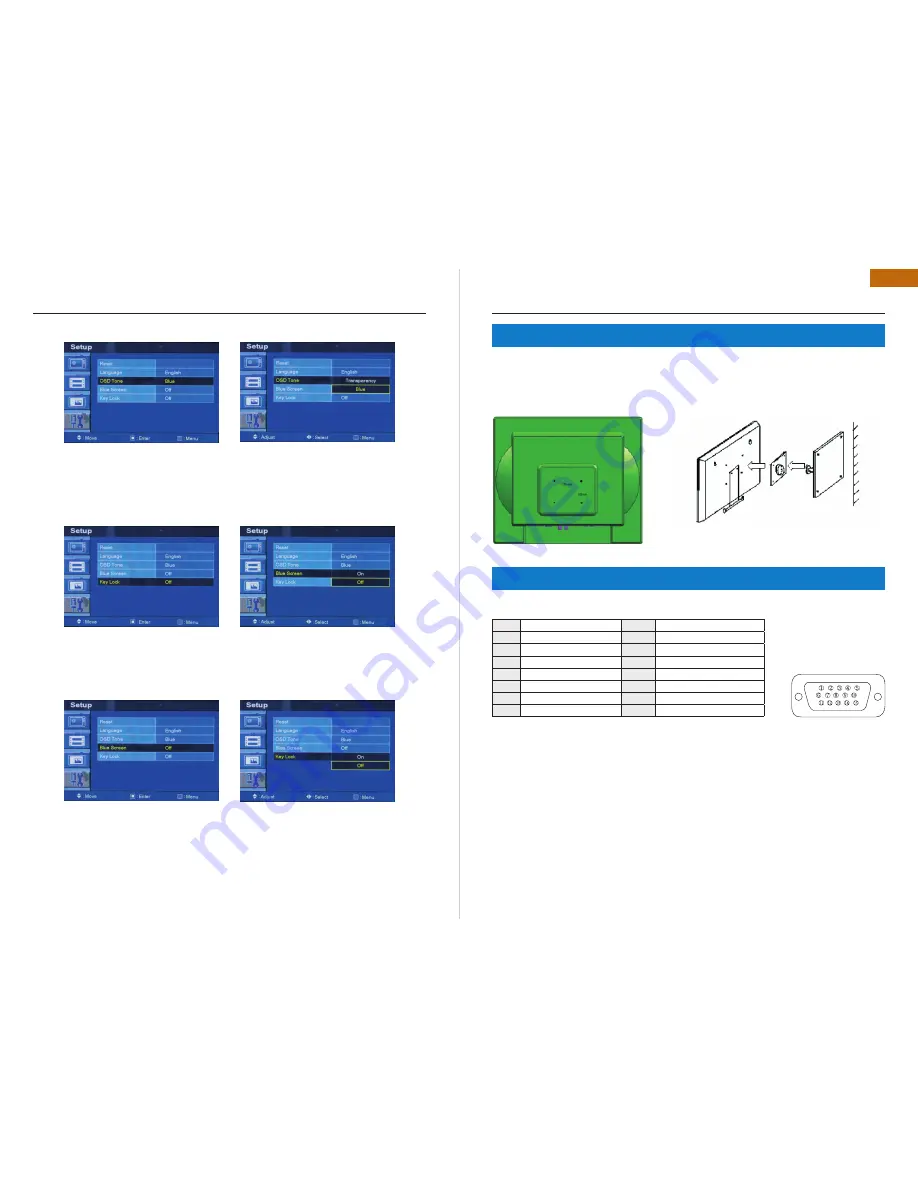
Press the up(
) / down(
) button to select
the OSD tone menu. Press the right(
) or
ENTER button
Press the up(
) / down(
) button to select
the desire OSD Tone. Press the MENU button
to save.
OSD Tone
Press the up(
) / down(
) button to select
the blue screen. Press the right(
) or ENTER
button.
Power cord
•
User’s manual
•
PC cable
•
Adaptor
•
Remote control
•
Batteries
•
Wall mount (option)
•
Rack mount (option)
•
Press the up(
) / down(
) button to select on
or off. Press the MENU button to save.
Blue Screen
Press the up(
) / down(
) button to select the
key lock menu. Press the right(
) or ENTER
button
Press the up(
) / down(
) button select on or
off. Press the MENU button to save.
Key Lock
7. MOUNTING GUIDE
8. D-SUB CONNECTOR PIN ASSIGNMENT
Wall mountable using two methods:
Using the 200 mm pre-cut holes
•
Using the VESA standard wall mount design and the 100mm hole pattern on the back panel to install the LCD
•
monitor to the wall.
ACCESSORY
PIN ASSIGNMENTS
Pin 1
Red Video
Pin 9
Pin 2
Green Video
Pin 10
Signal Cable Dectect
Pin 3
Blue Video
Pin 11
Ground
Pin 4
Ground
Pin 12
SDA (for DDC)
Pin 5
Ground
Pin 13
H-Sync.(or H+V Sync.)
Pin 6
Red Ground
Pin 14
V-Sync
Pin 7
Green Ground
Pin 15
SCL (for DDC)
Pin 8
Blue Ground
Monitor
Pad
Arm
Wall
D-SUB
Summary of Contents for ILM-17 PA
Page 16: ...www infinity cctv com ...


