P a g e
| 49
LT7185 Issue No 1 (04/17)
780 HD SERVICE / FAULT FINDING INSTRUCTIONS
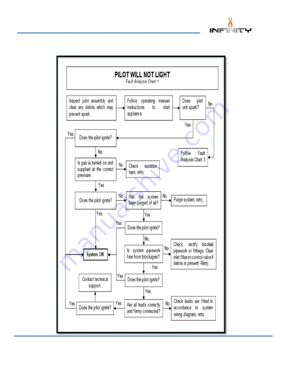
Fault Finding Charts
Page 1: ...This appliance is guaranteed for 12 months subject to conditions The 5 year extended parts warranty will only be valid if the annual service recommended in this manual has been completed and appliance...
Page 2: ...bed 17 Technical Specification 24 Siting the Appliance 25 Installation of the Appliance 33 Commissioning the Appliance 42 Annual Service Requirement 46 Fault Finding Charts 49 Wiring Diagram 52 Mainte...
Page 3: ...s England and Wales All installations must be notified to Local Area Building Control either directly or through a Competent Persons Scheme A Building Regulations Compliance Certificate will then be i...
Page 4: ...uppliers of heating products we take every care to ensure that the design and construction has to meet the general safety requirements when properly used and installed To this end our products are tho...
Page 5: ...off The odour produced is harmless and will disappear after a short period of time During the normal operation of the fire some black staining may appear on some parts of the fuel bed This is quite no...
Page 6: ...holding displays an UNLOCK graphic Fig 2 prompting the button to be pressed simultaneously Whilst both are pressed a progress bar Fig 3 will complete If either button is released before the progress b...
Page 7: ...on will cancel Mode select With the fire running on manual operation you can access three further modes Press for mode Use the selection wheel to cycle through the three options Auto Sleep and Light P...
Page 8: ...ter the mode options Auto is the first option press to enter auto mode Adjusting target temperature Use the selection wheel to increase or decrease the temperature to the desired level release your fi...
Page 9: ...Temperature display units use selector wheel to select either Celsius degree C or Fahrenheit degree F Press the button to save selection Gas fire pair code The device screen displays the current opera...
Page 10: ...Note Never operate the appliance when the glass panel is removed or broken The glass may discolour quickly when first installed and it should be cleaned This is due to the burning of the refractory f...
Page 11: ...ed after the loose components and moulded shapes have been removed from the 780 HD fire box It is important that all fuel bed shapes are positioned as shown in these instructions Fuel Bed Layout Fuel...
Page 12: ...No 1 04 17 780 HD USERS INSTRUCTIONS Slide ceramic strip L 380mm W 10mm H 15mm in behind Centre log piece and in front of the burner slots on the rear burner Side on view Slide air tray in to place m...
Page 13: ...T7185 Issue No 1 04 17 780 HD USERS INSTRUCTIONS Slide the LH base ceramic piece in to place Slide R H base ceramic in to place Split the pack of Embaglow in half Keep one half of the Embaglow for ann...
Page 14: ...SERS INSTRUCTIONS Stretch out half of the Embaglow like a net Lay the stretched out Embaglow along the front burner slots avoiding going pass the cross lighting lug Avoid getting the Embaglow fibers n...
Page 15: ...17 780 HD USERS INSTRUCTIONS Lay the Centre back log along the back of the rear burner making sure it is in the Centre and this pattern shown is facing forward and the flat edge is against the rear l...
Page 16: ...P a g e 15 LT7185 Issue No 1 04 17 780 HD USERS INSTRUCTIONS Place the two log shapes as shown Place the 1 log shapes as shown...
Page 17: ...P a g e 16 LT7185 Issue No 1 04 17 780 HD USERS INSTRUCTIONS This Centre log must be in line with the cross lighting lug on the front Centre log Place the 1 log shape as shown...
Page 18: ...17 LT7185 Issue No 1 04 17 780 HD USERS INSTRUCTIONS Walnut fuel bed Place the final 2 log shapes as shown Slide the Centre log shape behind the front burner Avoid placing the Centre log over the burn...
Page 19: ...17 780 HD USERS INSTRUCTIONS Slide ceramic strip L 380mm W 10mm H 15mm in behind Centre log piece and in front of the burner slots on the rear burner Side on view Slide air tray in to place make sure...
Page 20: ...T7185 Issue No 1 04 17 780 HD USERS INSTRUCTIONS Slide the LH base ceramic piece in to place Slide R H base ceramic in to place Split the pack of Embaglow in half Keep one half of the Embaglow for ann...
Page 21: ...SERS INSTRUCTIONS Stretch out half of the Embaglow like a net Lay the stretched out Embaglow along the front burner slots avoiding going pass the cross lighting lug Avoid getting the Embaglow fibers n...
Page 22: ...INSTRUCTIONS Lay the Centre back log along the back of the rear burner making sure it is in the Centre and this pattern shown is facing forward and the flat edge is against the rear liner Place the on...
Page 23: ...P a g e 22 LT7185 Issue No 1 04 17 780 HD USERS INSTRUCTIONS Place the 1 log shapes as shown Place the 1 log shape...
Page 24: ...P a g e 23 LT7185 Issue No 1 04 17 780 HD USERS INSTRUCTIONS This Centre log must be in line with the cross lighting lug on the front Centre log Place the final 2 log shapes as shown...
Page 25: ...240 VAC 50 60 Hz 0 2A Note The efficiency of the appliance has been measured as specified in BS7977 1 2009 A1 2013 and the net efficiency rate is 71 8 The gross calorific value of the fuel has been u...
Page 26: ...Safe installation and user Regulations All relevant parts of the local and national building regulations and all relevant recommendations of the following British standards Failure to do so could lead...
Page 27: ...surround with a 150 degree C minimum rating is required Class One That is a conventional brick or stone chimney as used for a solid fuel appliance with an effective cross sectional dimension of 225 x...
Page 28: ...surround design Check the fireplace details first Slide the fire box back into the catchment area and secure the fire box against the front face of the chimney breast Fit the fire place frame to the f...
Page 29: ...g e 28 LT7185 Issue No 1 04 17 780 HD INSTALLATION INSTRUCTIONS A B C Builder s opening aperture size when fitting hole in the wall plaster edge or slips A Hole in the wall using none combustible sli...
Page 30: ...80 HD INSTALLATION INSTRUCTIONS Using rawl plugs and wood screws retain the fire box via the 6mm holes within the slip brackets None combustible slips can now be fitted up to the edge of the fire plac...
Page 31: ...ng rawl plugs and wood screws New plaster board can now be fitted to cover the exposed metal work making sure that no plater joints are positioned directly above the unit as highlighted in the Fig 2 a...
Page 32: ...combustible material should be fitted inside the fireplace opening Installation with a flexible liner The 780 HD is designed for installation within the masonry chimney with or without a flexible lin...
Page 33: ...fire box assembly within the masonry aperture at the same time guiding the gather hood within the guides situated on the top of the fire box Please see Fig 2 Engage the hood studs within the slotted...
Page 34: ...Remove the 2 off screws retaining the ECU cover from the LH side of the burner carrier Lift off the cover plate to allow access to the ECU unit Within the ECU unit will be a clear port connection lab...
Page 35: ...mportant to have the cable socket facing the rear of the fire box Please note when installing the dongle with appliances using a four sided trim option The studs with the base of the fire box unit sho...
Page 36: ...appliance Gas inlet isolation device is located on bottom left hand side of the fire box the gas supply entry point is positioned at the rear bottom on left hand side With the appliance fixing kit is...
Page 37: ...cable through the side of the chimney breast It is good practice to run the cable within a sleeve of at least 15mm internal diameter sealing the sleeve using a suitable sealant at the point the sleev...
Page 38: ...tion Note When installing the appliance with a 3 inch 75mm rebated surround the option 30mm spacer frame Part No 7570 will be required The fire box assembly can be retained using the following two met...
Page 39: ...the complete assembly using suitable rawl plugs and wood screws via two 6mm holes within the wall fixing brackets Please see Figure 7 Please Note The fireplace frame is supplied with the slip guides...
Page 40: ...glass fascia Using A B C Builder s opening aperture size when fitting hole in the wall plaster edge or slips instructions on page 28 to place fire on the wall Secure fire in place to the wall with 4 s...
Page 41: ...7 780 HD INSTALLATION INSTRUCTIONS Slide fixing frame for the glass fascia over the studs and secure in place with 4 fixings nuts provided in kit Use the fixing nuts here Make sure the heat deflector...
Page 42: ...rform this test on this appliance Now the fire is ready for the glass fascia to be hooked on using the studs on the fascia sliding them in to place on the slots provided in the side of the fixing fram...
Page 43: ...t point screw from the inlet elbow and connect the pressure gauge Turn on the gas to the appliance at the isolation valve Light the appliance as described in the user instruction section Page 4 turn o...
Page 44: ...panel within the bottom retaining slot and push back against the seals Please see Fig 11 Non reflective glass option The non reflective glass has no print on the glass due to this there is a inner fra...
Page 45: ...nner provided with the appliance being careful not to over tighten the glass as this will cause breakages Position the top fixing bracket over the top edge of the glass panel and slide over the four M...
Page 46: ...f the fault cannot be corrected disconnect the fire from the gas supply and seek expert advice Spillage can be caused by a restriction in the flue system down draught or insufficient ventilation into...
Page 47: ...s you will still have a reflection in the glass liners Annual Service Requirement General Servicing should be carried out annually by competent person whose name appears on the gas safe register All G...
Page 48: ...x assembly Carefully remove the LH RH side panels Remove the rear panel from within the fire box Finally remove the eight screws from the inner and outer inspection covers Please see figure 1 With the...
Page 49: ...P a g e 48 LT7185 Issue No 1 04 17 780 HD SERVICE FAULT FINDING INSTRUCTIONS Spillage test Follow the procedure stipulated on page 45 of the installation instruction section...
Page 50: ...P a g e 49 LT7185 Issue No 1 04 17 780 HD SERVICE FAULT FINDING INSTRUCTIONS Fault Finding Charts...
Page 51: ...P a g e 50 LT7185 Issue No 1 04 17 780 HD SERVICE FAULT FINDING INSTRUCTIONS...
Page 52: ...P a g e 51 LT7185 Issue No 1 04 17 780 HD SERVICE FAULT FINDING INSTRUCTIONS...
Page 53: ...P a g e 52 LT7185 Issue No 1 04 17 780 HD MAINTENANCE INSTRUCTIONS Wiring Diagram Attach to the oxy pilot...
Page 54: ...emove the four screws retaining the gas inlet plate and the ECU cover Please see Fig 1 Shut off the restrictor elbow and disconnect the 8mm inlet nut Switch off the mains supply from the main supply p...
Page 55: ...compression nut on the supply pipe Remove three two screws retaining the burner assembly to the carrier and lift away from the injector Unscrew the locking nut holding the injector and silencer brack...
Page 56: ...s instruction section Remove the Loose shapes and the air tray assembly Switch off the mains supply from the main supply plug socket Undo the two M3 nuts retaining the ECU unit and remove the connecti...
Page 57: ...TIONS Short Spares List Component Part No Burner Bar 3057 Front Injector Mrk 220 A 6283 Rear Injector Mrk 290 3515 ODS Unit 7280 Control Valve 6590 Electrical Control Unit ECU 7150 Ignition Lead 6646...
Page 58: ...y filled out and record of annual services must be up to date and supported by receipts in each case 5 This warranty is not transferable and relates to the original installation only 6 The Registratio...
Page 59: ...extended five year parts warranty and the appliance must be registered by completing and return the registration document last page of this booklet to Infinity Fires Date of first service Engineers N...
Page 60: ...the manufacturer s instructions Hearth Requirements where fitted Is the hearth constructed from non combustible material Is the hearth a minimum of 12mm thick with a minimum floor to top surface of 5...
Page 61: ...nty Installer Details Name Company name Gas safe number Date of installation Your Details Name Address Post Code Telephone No Product Details Model 780 HD Serial No Date Of Purchase This information c...
Page 62: ...P a g e 61 LT7185 Issue No 1 04 17...
Page 63: ...P a g e 62 LT7185 Issue No 1 04 17...
Page 64: ...409 Grommet 1092 Silicone sealing strip 4818 Liners fitted sides rear top AAA Batteries x 4 Remote control handset Handset holder 7191 Airtray tried for fitment in firebox Top glass retaining bracket...