User Guide
17 of 44
Revision 1.0
2020-05-22
EVAL-M3-302F User Guide
iMOTION™ Modular Application Design Kit
Getting started with EVAL-M3-302F
5
Getting started with EVAL-M3-302F
In order to run the motor system, a combination of the iMOTION™ MADK control board (EVAL-M3-302F) and the
matching MADK power board (with M3 connector) is required. The iMOTION™ software tools, MCEDesigner and
MCEWizard, are also required to initially set up the system, as well as to control and fine-tune the system
performance to match users’ exact needs. This chapter provides more details on setting up the system and
getting started with the iMOTION™ MADK development platform.
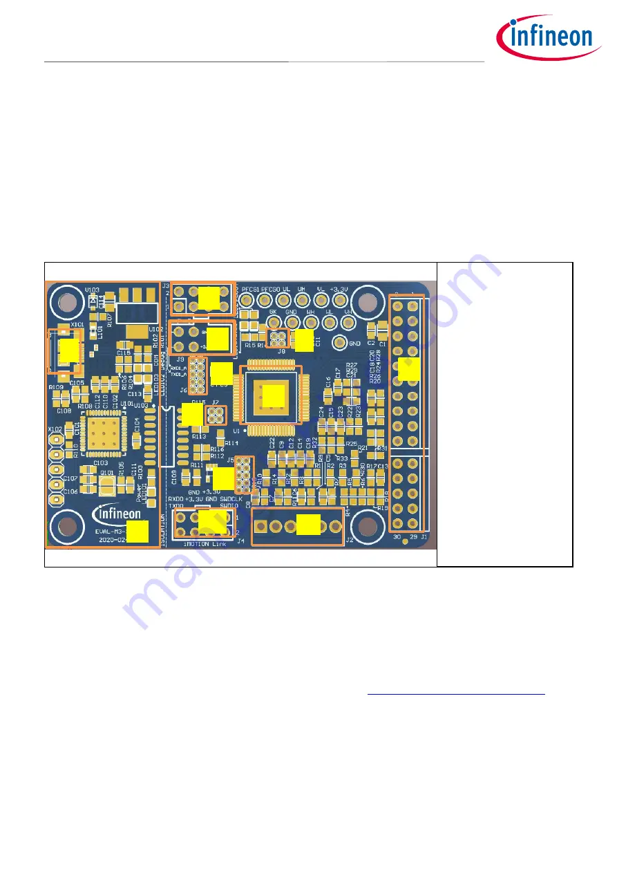
The EVAL-M3-302F consists of several functional groups, which enable an out-of-the-box, fully functional motor
control system combined with additional interfaces and test points for more advanced use cases. Figure 4
shows the functional groups of the EVAL-M3-302F evaluation board.
Figure 4
Functional groups of the EVAL-M3-302F evaluation board’s top side
5.1
Setting up the motion control engine (MCE)
After downloading and installing the iMOTION™ PC tools (MCEWizard and MCEDesigner), the following steps
need to be executed in order to run the motor. Refer to Chapters 5.2.1 and 5.2.2 as well as MCEWizard and
MCEDesigner documentation for more information.
1.
Get the latest IMC302A-F064 MCE software package available on
www.infineon.com/imotion-software
website.
2.
Connect PC-USB connector on the on-board debugger to the PC via USB cable.
3.
Connect EVAL-M3-302F M3 30-pin interface connector (J1) to power board (for example EVAL-M3-CM615PN,
see Figure 5).
4.
Use MCEWizard to enter the target motor’s system and operating parameters, as well as the hardware
parameters of the evaluation board, which will then be used to calculate controller’s digital parameter set
representing complete motor drive system. First click “Calculate” button on the “Verify & Save Page” and
then save the drive parameter set into your project directory by clicking “Export to Designer file (.txt)”.
5
6
2
1
8
1.
On-board debugger
2.
USB interface
connector (X101)
3.
MCU core UART0 and
SWD connecter (J3)
4.
MCU core UART1
connecter (J9)
5.
Signal pin (J8)
6.
Signal pin (J6)
7.
IMC302A-F064
iMOTION™ motor
control IC
8.
Signal pin (J7)
9.
Signal pin (J5)
10.
iMOTION™ link
connector(J4)
11.
Hall sensor input
connecter (J2)
12.
iMOTION™ MADK-M3
30-pin interface
connector (J1)
11
7
4
3
10
12
9


