background image


User Guide 

10 of 32 

002-29388 Rev. *B  


2022-06-15 


EZ-

PD™ BCR HPI Utility user guide


EZ-

PD™ BCR HPI Utility


2.4


USB-C port information 


This section shows the general USB-C port information when connected to EZ-PD

 BCR device based on HPI 

registers defined in the BCR HPI specification.  

Table 3


USB-C ports and corresponding BCR HPI register 

Item 

Description 

Register reference in BCR HPI specification 

Status 

Port connection information and 
device information to the port

’s 

partner  

TYPE_C_STATUS register (Bit 0: Port partner 
connection status) and READ_SILICON_ID 

VBUS voltage 

Live voltage (V) information on 
VBUS supply 

BUS_VOLTAGE register 

Selected voltage 

Selected VBUS voltage (V)  

CURRENT_PDO 

Polarity 

CC polarity information  

TYPE_C_STATUS register (Bit 1: CC polarity) 

PD contract 

PD spec revision supported by 
BCR 

PD_STATUS register (Bit 16-18: Partner 
(attached device) PD spec revision) 

Requested current 

Operating current (A) information 
in RDO  

CURRENT_RDO 

Roles 

Current port data role information 
and current power role 
information of BCR 

PD_STATUS register (Bit 6: Current port data 
role and Bit 8: Current port power role) 

Capability 
mismatch 

Capability mismatch bit in RDO 

CURRENT_RDO 

Max available 
current 

Maximum operating current (A) 
information in PDO 

CURRENT_PDO 


2.5


Tabs 


This section provides specific tabs to read and write HPI registers using the EZ-PD

 BCR HPI Utility. Note that 

each tab in EZ-PD

 BCR HPI Utility is automatically enabled or disabled depending on the connected BCR 

device

’s

 capability as follows:  

Table 4


Supporting tab information per BCR device 

Device 

Tab 
Adapter 

Adapter-PPS  GPIO 

Registers 

Events 

Config 

BCR 
(CYPD3177) 

Yes 

No 

Yes 

Yes 

Yes 

No 

BCR-PLUS 
(CYPD3176) 

Yes 

Yes 

No 

Yes 

Yes 

Yes 

BCR-LITE 
(CYPD3178) 

No 

No 

No 

Yes 

Yes 

Yes 


Summary of Contents for EZ-PD

Page 1: ...atform GUI to communicate with EZ PD BCR BCR PLUS and BCR LITE devices through HPI Intended audience This document is intended for anyone who using the EZ PD BCR HPI Utility Abbreviations and definitions Table 1 Abbreviations Acronyms Meaning BCR Barrel Connecter Replacement GUI Graphical User Interface HPI Host Processor Interface PC Personal computer PD Power Delivery PDO Power Data Object PPS P...

Page 2: ... port information 10 2 5 Tabs 10 2 5 1 Adapter tab 11 2 5 2 Adapter PPS 12 2 5 3 GPIO 13 2 5 4 Registers 14 2 5 5 Events 15 2 5 6 Config 16 2 6 Demo BCR sink PDOs configuration 17 2 6 1 Identify BCR s sink PDOs 17 2 6 2 Configure BCR s sink PDOs 18 2 6 3 Apply the configured sink PDO 19 2 6 4 View HPI raw data optional 20 2 7 Demo PPS configuration 22 2 7 1 Identify power adapter source PDOs 22 2 ...

Page 3: ...e prerequisites 1 2 Hardware setup Hardware setup is different for each BCR device and its corresponding EVK For the BCR CYPD3177 device and CY4533 EZ PD BCR EVK a MiniProg3 CY8CKIT 002 or a MiniProg4 CY8CKIT 005 device is required as the USB to I2C bridge between the EZ PD BCR device and PC OR USB Type C Power Adaptor CY4533 EZ PD BCR EVK Your Design MiniProg3 or MiniProg4 PC Power Load EZ PDTM B...

Page 4: ...PD BCR LITE EVK neither the MiniProg3 nor MiniProg4 device is required as these two EVKs have dedicated USB to I2C bridge controller on the board OR USB Type C Power Adaptor CY4534 EZ PD BCR PLUS EVK PC Power Load EZ PD BCR HPI Utility EZ PDTM BCR PLUS USB Type C USB I2C bridge HPI CY4535 EZ PD BCR LITE EVK EZ PDTM BCR LITE USB I2C bridge HPI USB Micro B Figure 3 Hardware setup for using EZ PD BCR...

Page 5: ...Introduction Figure 4 EVK jumper settings CY4534 EZ PD BCR PLUS EVK and CY4535 EZ PD BCR LITE EVK 1 3 Technical support For assistance go to Infineon developer community https community infineon com first to search for or start discussion or visit to https www infineon com support ...

Page 6: ... 2022 06 15 EZ PD BCR HPI Utility user guide EZ PD BCR HPI Utility 2 EZ PD BCR HPI Utility 2 1 Installation 1 Download the installer file and double click it 2 Accept License Agreement and click Next Figure 5 End user license agreement ...

Page 7: ...BCR HPI Utility 3 Select the folder location where you want to install and click Next Figure 6 Select destination location 4 Choose the option whether to launch program automatically after Finish button or exit installation without executing the program Figure 7 Installation completion ...

Page 8: ...ly with one of followings a Shortcut icon created in desktop screen b Windows Start menu Windows Start Search Type as EZ PD BCR Figure 8 Shortcut icon image 2 2 Basic layout The EZ PD BCR HPI Utility consists of connection USB C port information specific HPI tabs and a status bar Connection USB C Port Information Tabs Status Bar Menu Figure 9 Basic screen of EZ PD BCR HPI Utility ...

Page 9: ...nected power adapter status The GUI is now ready to communicate with the BCR device and obtain more information about the connection between the BCR device and power source PD controller Figure 12 Adapter attached and HPI Established The third item in the Status bar also shows the result of the last HPI communication When the EZ PD BCR HPI Utility is initially launched the default status is shown ...

Page 10: ...tract PD spec revision supported by BCR PD_STATUS register Bit 16 18 Partner attached device PD spec revision Requested current Operating current A information in RDO CURRENT_RDO Roles Current port data role information and current power role information of BCR PD_STATUS register Bit 6 Current port data role and Bit 8 Current port power role Capability mismatch Capability mismatch bit in RDO CURRE...

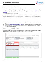
Page 11: ...CR s sink PDOs config Figure 14 Adapter tab 1 BCR power sink capabilities This provides information on Sink PDOs of the BCR device Click Read Sink PDOs to display the list of sink PDOs with the following operations Write Read_SINK_PDO See PD_CONTROL in the BCR HPI specification Receive Read PDO data response See Response Codes in the BCR HPI specification Read Sink PDOs from Data Memory See Data M...

Page 12: ... Read Source PDOs from Data Memory See Data Memory in the BCR HPI specification 3 BCR s Sink PDOs Config This part enables you to configure Sink PDOs See Demo BCR sink PDOs configuration 2 5 2 Adapter PPS The Adapter PPS tab enables you to request the PPS output voltage and current value to the PPS source The PPS feature is supported only by the BCR PLUS device in the BCR family Unless you are con...

Page 13: ...hat only the CYPD3177 BCR device provides GPIO feature If you use CYPD3176 or CYPD3178 device the GPIO tab is automatically disabled You can also refer to the EZ PD BCR datasheet for details on GPIO_1 Figure 16 GPIO tab Analog input From GPIO1 Drive Mode you can select the drive mode See SET_GPIO_MODE in the BCR HPI specification When you select the Analog Input option you can read the GPIO_1 volt...

Page 14: ... PD BCR HPI Utility communicates with the connected BCR device Figure 18 Registers tab Table 5 Register list and HPI specification references Register address Register name 0x0000 DEVICE_MODE 0x0002 SILICON_ID 0x0006 INTERRUPT 0x0010 READ_ALL_VERSION 0x1008 PD_STATUS 0x100C TYPE_C_STATUS 0x100D BUS_VOLTAGE 0x1010 CURRENT_PDO 0x1014 CURRENT_RDO 0x1024 EVENT_MASK 0x1028 SWAP_RESPONSE 0x1044 EVENT_ST...

Page 15: ...tility user guide EZ PD BCR HPI Utility 2 5 5 Events The Events tab displays response codes upon commands and events generated from the device and PD state changes Click Clear Events to clear the list of events already displayed under this tab Figure 19 Events tab ...

Page 16: ...Config The Config tab allows you to read and write specific HPI registers such as FET OVP and OCP control registers Click Read in All Configs to read and update all registers You can configure specific registers by reading and writing a single individual register or all registers together Figure 20 Config tab ...

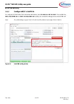
Page 17: ...ing current Change the Sink PDOs based on your system requirements This section provides a simple example of how to configure BCR Sink PDOs Note 1 All settings for the power contracts are volatile If power is recycled removed the contract goes back to default values 2 Instructions in Demo BCR sink PDOs configuration use CY4533 EZ PD BCR EVK using the CYPD3177 device 3 The specific pin information ...

Page 18: ...o configure the Sink PDOs of the connected BCR device select Enable User PD Contract This enables the BCR s Fixed PDO List and BCR s Variable PDO List so that you can edit the voltage and current of PDO List Note The valid voltage range is from 5 V to 20 V and the valid current range is from 0 A to 5 A Figure 22 Sink PDO configuration ...

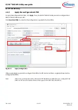
Page 19: ...s to the BCR device over HPI Click Read Sink PDOs to verify that the configuration is applied to the Sink PDOs Figure 23 Apply configuration If the power adapter supports the configured Sink PDOs the PD contract will be re negotiated based on the configured Sink PDOs Note If the rotary switch position of the CY4533 EZ PD BCR EVK is modified the user configured Sink PDOs are removed and restored ba...

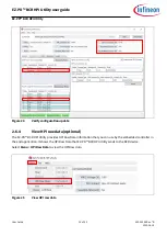
Page 20: ...ration update 2 6 4 View HPI raw data optional The EZ PD BCR HPI Utility provides HPI Raw Data information that you can use by the embedded controller in the end application It shows the HPI Raw Data that EZ PD BCR HPI Utility sends to the BCR device Select Menu HPI Raw Data to view the HPI Raw data Figure 25 View HPI raw data ...

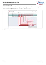
Page 21: ...pply again on BCR s Sink PDOs Config in the Adapter tab you can view the HPI Raw Data of your BCR device s Sink PDO configuration Optionally click Save to save it in text format BCR Device Address HPI Register Address Address Signature SNKP Sink Fixed PDO Sink Variable PDO Sink PDO Mask Figure 26 HPI raw data ...

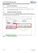
Page 22: ...ple is applicable only when you use a PPS adapter source and BCR PLUS CY4534 EZ PD BCR PLUS EVK 2 7 1 Identify power adapter source PDOs To identify power adapter source PDOs click Read Source PDOs The current Source PDOs is shown in the Power Adapter Power Source Capabilities table If the power adapter supports the PPS feature PPS APDO lists are automatically populated in the PPS APDO List table ...

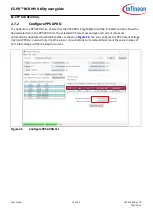
Page 23: ...Enabled column shows the desired selection in the PPS APDO list The selected PPS maximum voltage and current values are automatically duplicated to editable textbox as shown in Figure 28 You can configure the PPS Output Voltage mV and PPS Op Current mA Click the plus or minus buttons to increment decrement the value in steps of 20 mV for voltage and 50 mA step for current Figure 28 Configure PPS A...

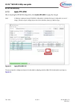
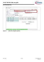
Page 24: ...n click Update PPS APDO to apply the changes Note A Warning message during PPS APDO configuration indicates that your configuration is out of range Check the input configuration and ensure that the values are within range Figure 29 Apply PPS APDO list The new values for voltage and current contracted are displayed in the USB C Port information as shown in Figure 30 ...

Page 25: ...User Guide 25 of 32 002 29388 Rev B 2022 06 15 EZ PD BCR HPI Utility user guide EZ PD BCR HPI Utility Figure 30 Verify PPS configuration updates ...

Page 26: ...rialI2C 0 Note that it is not a unique string it varies depending on the number of USB I2C connections and repeated connection disconnection Optionally you can change the USB I2C serial number string using the USB Serial Configuration Utility via USB Serial SDK Installer Run the USB Serial Configuration Utility and connect the CY4534 EZ PD BCR PLUS EVK or CY4535 EZ PD BCR LITE EVK to the PC Select...

Page 27: ...BCR HPI Utility user guide EZ PD BCR HPI Utility Figure 32 Serial number change and program After programming is completed remove the USB connection and reconnect it to reset the system You can now verify the new serial number in the EZ PD BCR HPI Utility ...

Page 28: ...User Guide 28 of 32 002 29388 Rev B 2022 06 15 EZ PD BCR HPI Utility user guide EZ PD BCR HPI Utility Figure 33 Verify new serial number changed ...

Page 29: ...3 4 device Close the other utility that uses MiniProg3 4 Adapter Disconnected is not changed to Adapter Connected when you click Start Wrong MiniProg3 4 or USB I2C selection If multiple MiniProg3 4 and USB I2C devices are connected to the PC check if the connection option in EZ PD BCR HPI Utility is correctly selected by physically connected BCR EVK BCR device does not turn on Verify that BCR devi...

Page 30: ...arrel Connector Replacement BCR 2 CY4533 EZ PD BCR evaluation kit 3 CY4534 EZ PD BCR PLUS evaluation kit 4 CY4535 EZ PD BCR LITE evaluation kit 5 BCR Host Processor Interface Specification 6 CY8CKIT 002 PSoC MiniProg3 program and debug kit 7 CY8CKIT 005 MiniProg4 Program and Debug kit 8 USB serial SDK installer ...

Page 31: ... sink PDOs and Troubleshooting Added section View HPI raw data optional Updated Table 5 Figure 9 Figure 14 Figure 18 Figure 20 Figure 22 Figure 23 Figure 24 and Figure 25 Added note in Demo BCR sink PDOs configuration 2022 06 15 B Updated overall content as per the latest release of EZ PD BCR HPI Utility which also supports the BCR PLUS and BCR LITE devices of the EZ PD BCR product family Updated ...

Page 32: ...ustomer s applications The data contained in this document is exclusively intended for technically trained staff It is the responsibility of customer s technical departments to evaluate the suitability of the product for the intended application and the completeness of the product information given in this document with respect to such application For further information on the product technology ...

Reviews: