


User guide
14 of 32
V. 1.0
2020-11-03
EVAL-M1-101TF user guide
iMOTION™ Modular Application Design Kit
System and functional description
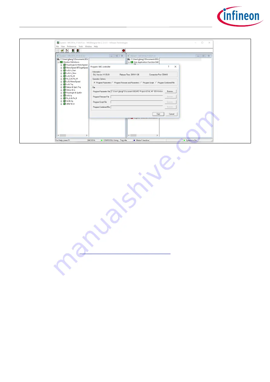
Figure 10
“Program IMC Controller” pop-up window
After the “Drive System Parameter” file has been programmed into the IMC101T controller, and the motor drive
system is powered, the MCEDesigner can be used to start/stop the motor, display motor current traces, change
the motor speed, modify drive parameters, and many other functions. Please refer to the MCEDesigner
documentation for more details.
Note:
The on-board debugger section of EVAL-M1-101TF is galvanically isolated from the controller
section and the attached power board. In order to program the parameters or firmware to the
IMC101T-F048 controller, the 3.3 V DC voltage needs to be supplied to the controller portion of the
EVAL-M1-101TF. This voltage can either be supplied by the power board (MADK power boards are
designed to supply the 3.3 V to the control board through M1 or M3 connector) or by feeding the 3.3
V DC voltage to the control board through some of the available 3.3 V access/test points, if the
power board is not attached to the EVAL-M1-101TF control board.
All the latest firmware files for different types of iMOTION
TM
control ICs are available for download via the
Infineon iMOTION
TM
website (
http://www.infineon.com/imotion-software
).